Testing functions, Diagnostics and Fault Elimination
S7-300 Programmable Controller Hardware and Installation
A5E00105492-01
10-27
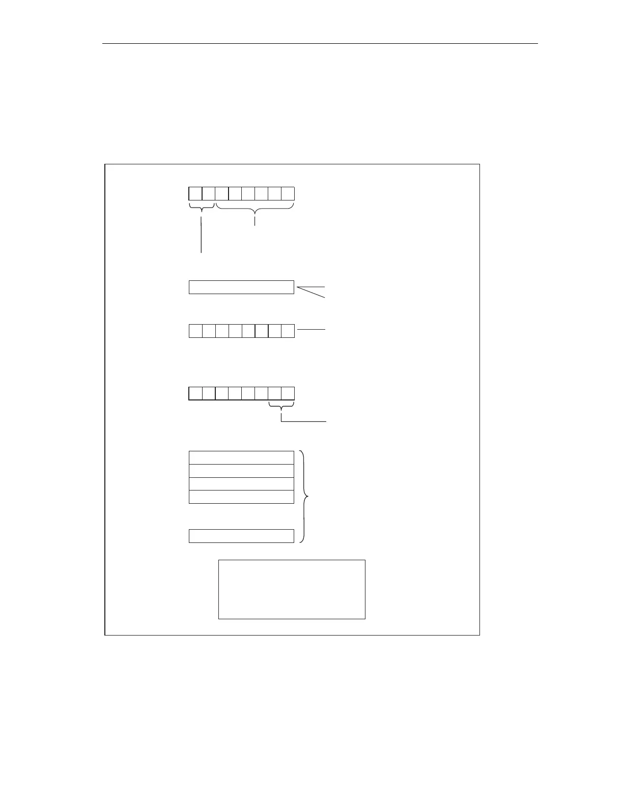
Interrupt status
The interrupt status of module diagnostics provides details on a DP slave. The
maximum length of module diagnostics starting at byte y is 20 bytes.
The following figure describes the structure and content of the bytes for a
configured address area of intermediate memory.
Byte y +1
01 : Code for diagnostic
interrupt
H
Byte y +4
to
Byte y +7
Byte y
Length of device-related diagnosis incl.
byte y (max. 20 bytes)
Code for device-related diagnosis
Byte y +3
Slot No:
2 = CPU
4...35 = No of configured
area of intermediate memory
00 = process interrupt
01 = incoming diagnosis
(there is at least one 1 )
10=outgoing diagnosis
11=reserved
error
Byte z
7 654 3210 BitNo..
00
76 543 210BitNo.
example on Byte y+2:
CPU = 02
1. Address area = 04
2. Address area = 05
H
H
H
etc.
Byte y +2
000
0
00
Diagnostics or interrupt data
(see figure 10-11)
.
.
.
Figure 10-10 Structure of the interrupt status for CPU 31xC
As of byte y+4
The significance of the bytes following byte y+4 depends on byte y+1 (see previous
figure).

 Loading...


