Maintenance
7-14
Automation System S7-400 Hardware and Installation
A5E00850741-01
7.8 Replacing Fans in the Fan Subassembly During
Operation
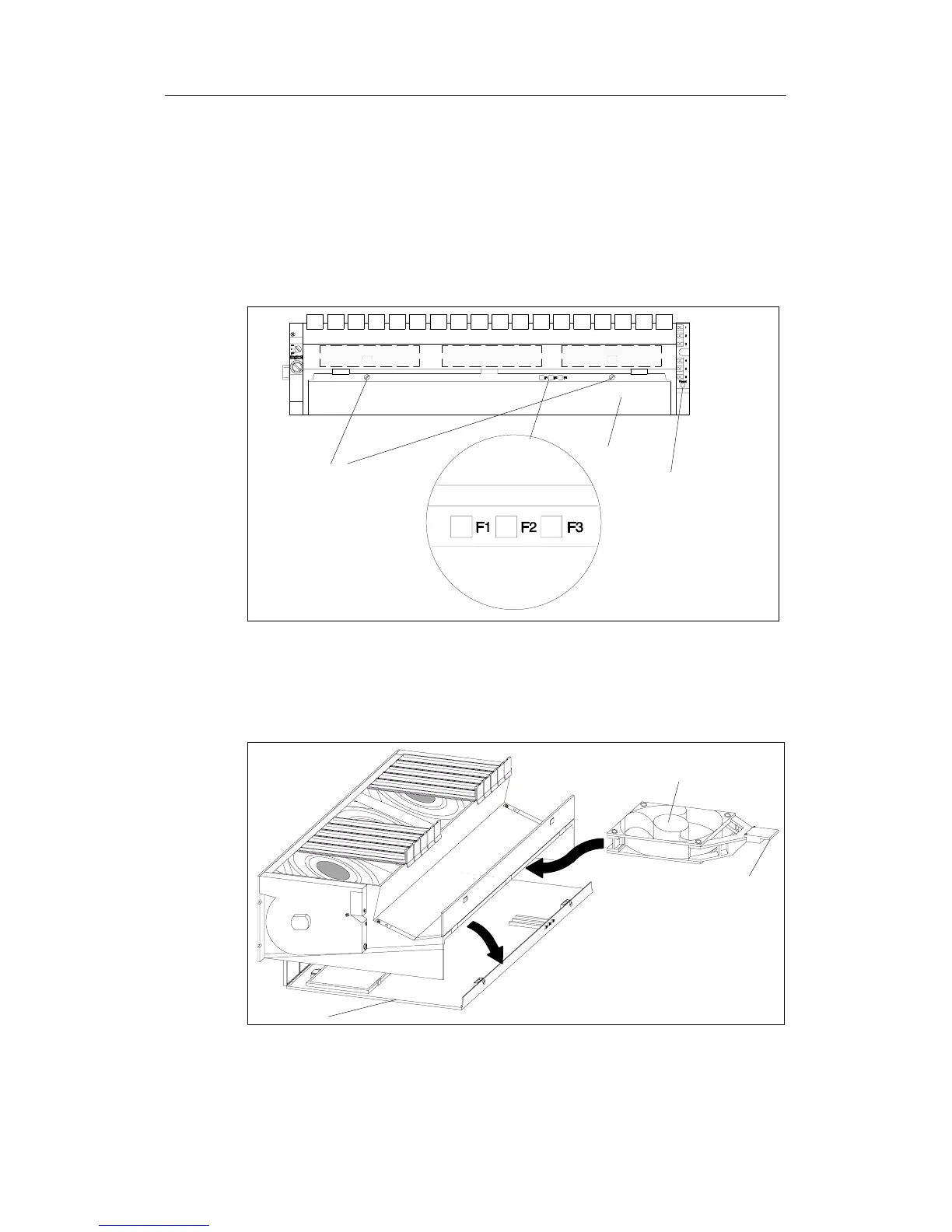
Removing the Fans
1. Use a screwdriver to make a quarter turn counter-clockwise and open the two
quick-release locks on the front of the fan subassembly.
Fan 1 Fan 2 Fan 3
LEDs:F1=Fan1
F2=Fan2
F3=Fan3
Quick-release locks
Reset button
Base
2. Grasp the base with both hands, press it down slightly and pull it fully out of the
fan subassembly.
3. Release the fan to be replaced by pressing the fan grip away from the housing
with your thumb.
Fan
Base
Fangrip
4. Pull out the fan to be replaced.

 Loading...


