Assembling and Installing Systems
A-30
Automation System S7-400 Hardware and Installation
A5E00850741-01
A.10 How to Protect Digital Output Modules against
Inductive Surge
Inductive Surge Voltage
Overvoltage occurs when inductive devices are switched off. Examples are relay
coils and contactors
Integrated Surge Arrester
S7-400 digital output modules are equipped with an integrated surge arrester
Additional Overvoltage Protection
Inductive devices require additional surge arresters only in following cases:
• If SIMATIC output circuits can be switched off by additionally installed contacts
(e.g. relay contacts).
• If the inductive loads are not controlled by SIMATIC modules.
Note: Consult the supplier of the inductors for the ratings of surge suppression
devices.
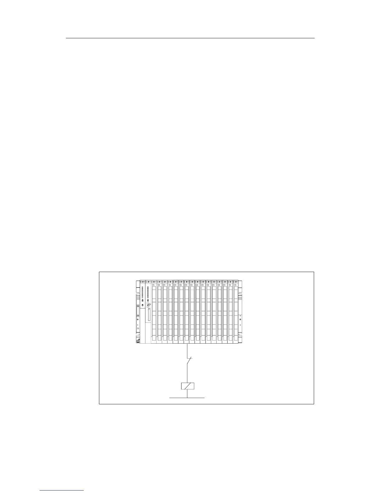
Example
Figure A-8 shows an output circuit that requires additional surge arresters.
Contact in output circuit
Inductivitys requires a circuiting
(see Figures A-9 and A-10)
D
Figure A-8 Relay Contact for EMERGENCY OFF in the Output Circuit

 Loading...


