Addressing the S7 -400
3-6
Automation System S7-400 Hardware and Installation
A5E00850741-01
3.3 How to Determine the Default Address of a Channel
Channel on a Digital Module
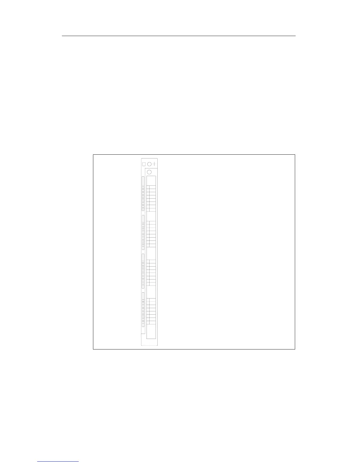
A channel on a digital module is addressed bit-wise. For a digital input module with
32 inputs, four bytes (starting with the default address of the module) are used to
address the inputs, and for a digital input module with 16 inputs, two bytes are
used. Bits 0 to 7 in these bytes are then reserved by the individual inputs (from top
to bottom).
This is clarified by the following figure with the example of a digital input module
with 32 channels at slot 12 (default address 44). With a digital output module, the
first character is a Q instead of an I.
I 44.0
I 44.1
I 44.2
I 44.3
I 44.4
I 44.5
I 44.6
I 44.7
I 45.0
I 45.1
I 45.2
I 45.3
I 45.4
I 45.5
I 45.6
I 45.7
I 46.0
I 46.1
I 46.2
I 46.3
I 46.4
I 46.5
I 46.6
I 46.7
I 47.0
I 47.1
I 47.2
I 47.3
I 47.4
I 47.5
I 47.6
I 47.7
Channel addresses

 Loading...


