Maintenance
7-20
Automation System S7-400 Hardware and Installation
A5E00850741-01
You can replace an interface submodule w ith another one without having to remove
the associated CPU from the rack. Follow the steps outlined below:
1. Switch the CPU to STOP (not the synchronization module of a redundant
system).
2. Switch off the power supply (not the synchronization module of a redundant
system).
3. Loosen the screws of the sub-D-connector and remove all connectors.
4. Loosen the two captive slot-head screws which secure the front plate of the
interface submodule to the left frame of the card slot so that the screws can be
removed by 6 mm.
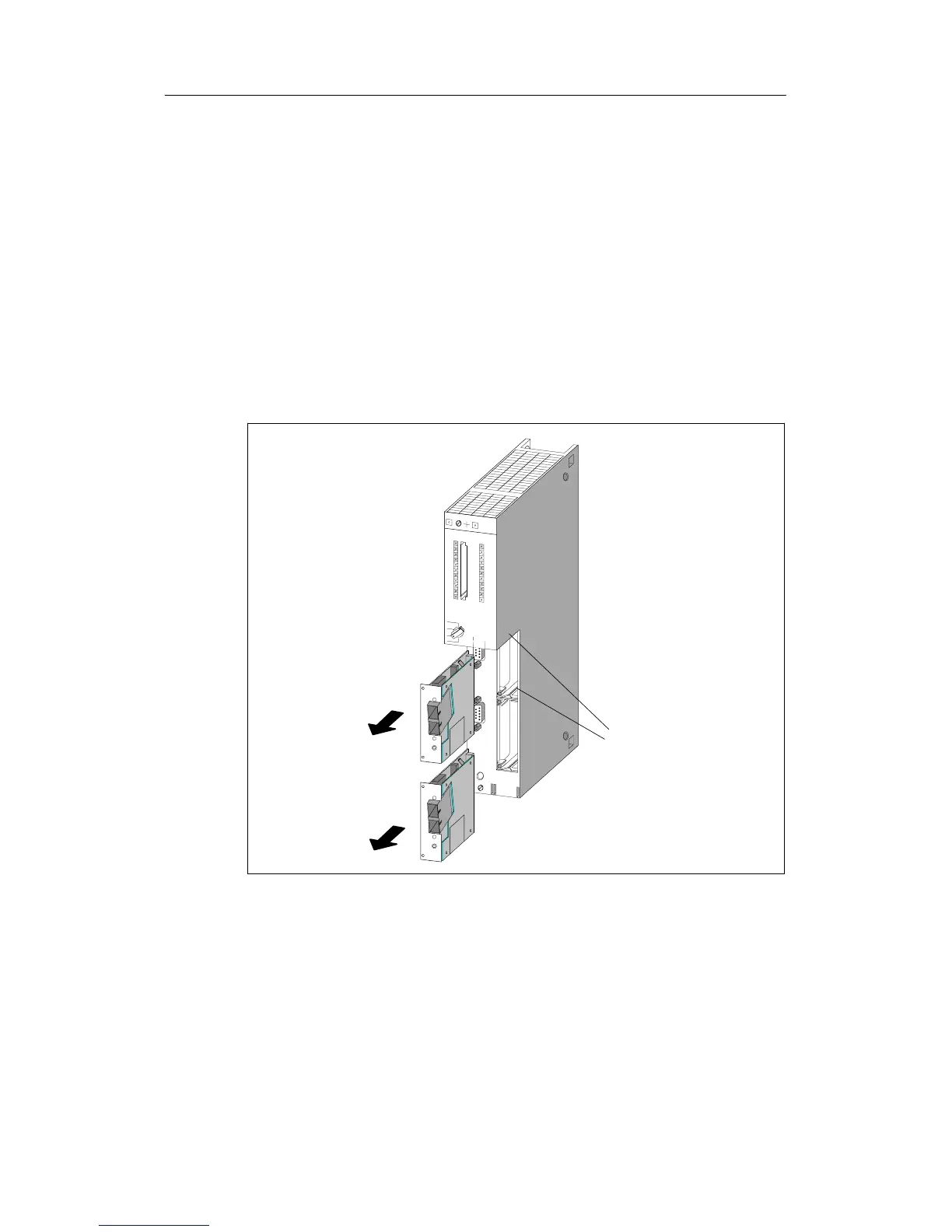
5. Carefully remove the interface submodule from the guide support of the card
slot (see figure 7-1). Hold the interface module on the long sides of the front
plate.
Guide
rails
Figure 7-1 Inserting an Interface Submodule in a CPU
Installing Interface Submodules
In order to install an interface submodule, proceed in reverse order. For further
information, see section 6.10 ”Installing Interface Submodules”.

 Loading...


