Installing the S7-400
2-35
Automation System S7-400 Hardware and Installation
A5E00850741-01
2.16 Accessories
Accessories
Some of the accessories needed for fitting the modules in the rack are provided in
the packaging of the modules and racks. The front connectors of the signal
modules must always be ordered separately. There are also optional accessories
for some modules.
The accessories for modules and racks are listed and briefly explained in
Table 2-3. A list of spare parts for SIMATIC S7 can be found in the Reference
Manual, Appendix C as well as in the c urrent CA 01 catalog.
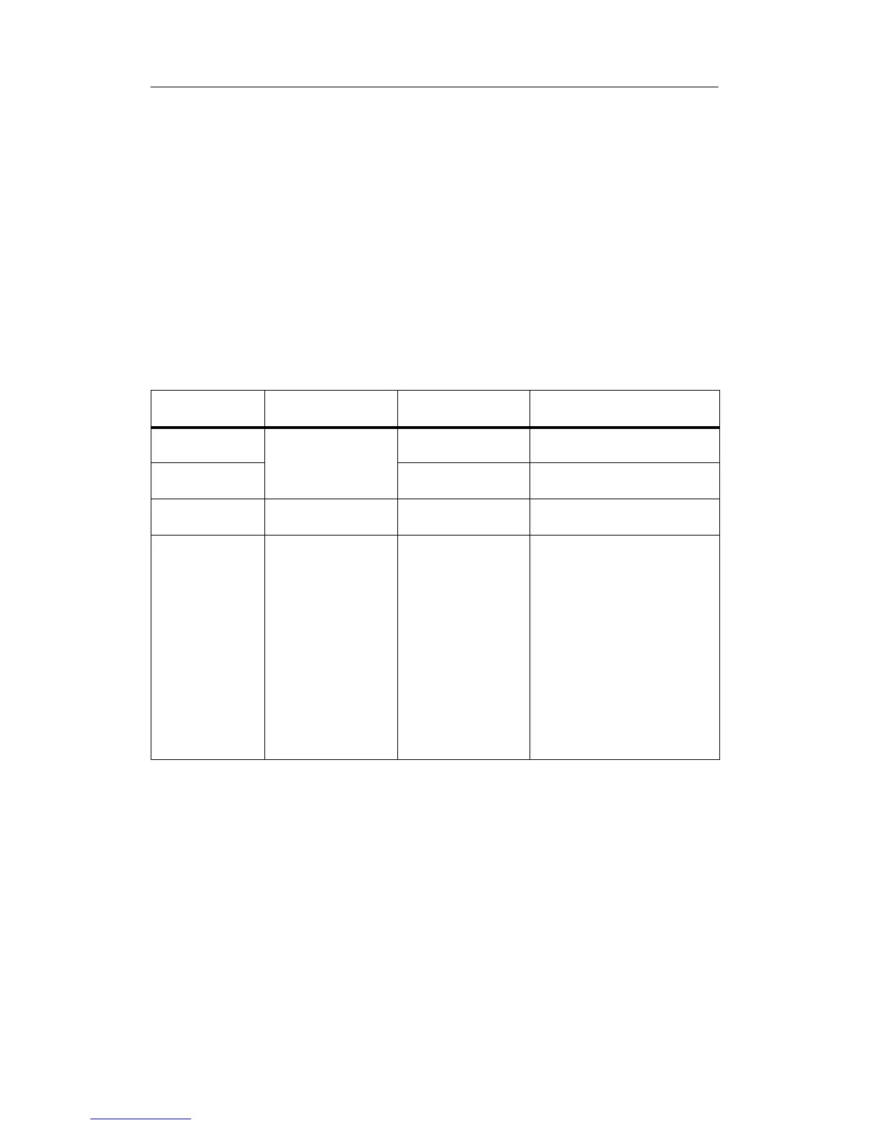
Table 2-3 Accessories for Modules and Racks
Module
Accessories
Supplied
Accessories Not
Supplied
Purpose of the Accessory
Rack (UR, CR,
ER)
Number wheel with
slot labels
-- For identifying the modules with
slot labels
Power Supply
Module (PS)
-- 1 or 2 backup
batteries
For central backup of RAM areas
in the CPU
CPU -- Memory cards Load memories required for the
CPU
Signal Module
(SM)
2 labels
Plate with pinout
--
--
For labeling the inputs and
outputs on the front connector
To identify the pinout of the front
connectors
-- Front connector with
strain relief for screw,
crimp or spring-type
terminal
For wiring the SMs
--
--
--
Extraction tool (for
crimp terminals)
Crimp contacts
Crimping tool
For rewiring SMs with a front
connector with crimp terminals

 Loading...


