Installing the S7-400
2-22
Automation System S7-400 Hardware and Installation
A5E00850741-01
2.9 Installing the Fan Subassembly
Procedure
1. Remove the left cover from the fan subassembly.
Using a 17 mm open-ended wrench, slacken the quick-release lock a quarter
turn.
Pull out the left cover of the fan subassembly. To do this, move the left cover
parallel to the fan subassembly in order to avoid damaging the plug-in contact
on the other side.
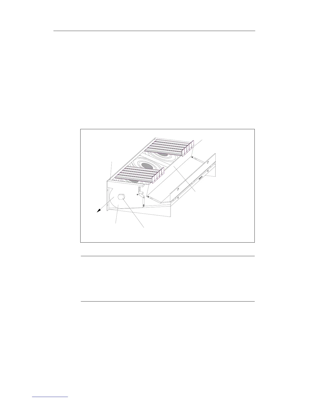
The following figure s hows you how to remove the left c over.
Left cover
Quick-release lock
Plug-in contact
Snap-in mechanism
of dummy covers
Back of cable
routing
Direction for
pulling off
Note
Provide the fan subassembly with dummy plates beneath free slots, this will
ensure optimum ventilation.
The fan subassembly is supplied with 18 dummy plates, arranged as 2 units, each
with 9 individual dummy plates. By breaking at one of the rupture joints, you can
split up the individual plates as required.
2. Remove the dummy plates which are not required by slackening the snap-in
mechanisms of the covers and pulling them off.
3. Break off as many dummy plates as required.

 Loading...


