Installing the S7-400
2-23
Automation System S7-400 Hardware and Installation
A5E00850741-01
4. Attach the dummy plates to the free slots:
-- Place the dummy plates on the rear wall of the cable routing,
-- Push the dummy plates back so that the noses of the dummy plates will fit
into the cutouts provided,
-- Push the dummy plates in until the snap-in mechanism engages in the
openings on the back of the cable r outing.
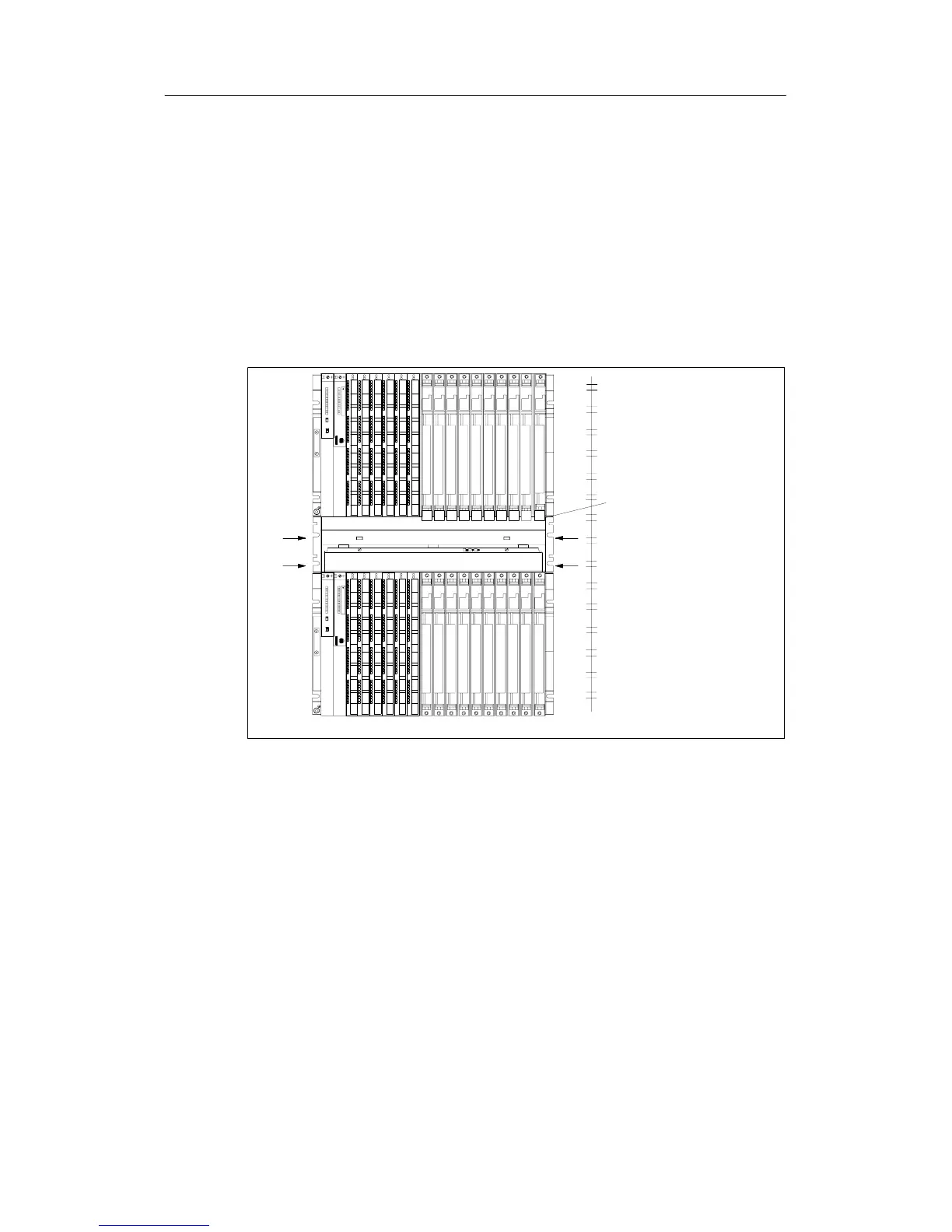
5. Then install the fan assembly in the 19-inch pitch directly under the rack or
between two r acks. Use M6 size screws for mounting.
The following figure shows how to mount the fan subassembly between two
racks.
Blanking
cover
19-inch
reference level
9101112131415161718
9101112131415161718
6. Refit the left cover.
7. Secure the left cover with the quick-release lock.
Monitoring the Fan Subassembly
To monitor the functioning of the fan subassembly via your program, connect the
outputs to a digital module.
Further details on the monitoring concept can be found in the Reference Manual,
Chapter 9.

 Loading...


