Installing the S7-400
2-10
Automation System S7-400 Hardware and Installation
A5E00850741-01
2.5 Mounting and Grounding the Racks
Important Notes on Installation
The S7-400 racks are designed for wall mounting, mounting on rails, and for
installation in frames and cabinets. Their mounting dimensions are compliant with
DIN 41 494.
According to the UL/CSA and the EU Directive 73/23/EEC (low-voltage directive),
installation in a cabinet, a casing, or a closed operations room is necessary in order
to fulfil the requirements for electrical safety (see
Reference Manual, Chapter 1).
Step 1: Retaining Distances Between Devices
You must observe the minimum distances between the rack and neighboring
devices. You need these minimum clearances during installation and operation.
• For fitting and removing modules
• For fitting and disconnecting the module front connectors
• To ensure the air flow required for cooling the modules during operation
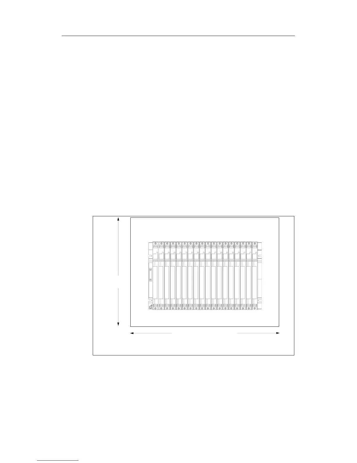
The following figure shows the minimum space you must provide for a rack.
20 mm
20 mm
40 mm
22 mm
352 mm
Mounting depth, fitted: max. 237 mm
40 mm facilitates the mounting of a fan subassembly
*
*
123456789101112131415161718
523 mm (18 slots)
298 mm (9 slots)
173 mm (4 slots)

 Loading...


