Assembling and Installing Systems
A-22
Automation System S7-400 Hardware and Installation
A5E00850741-01
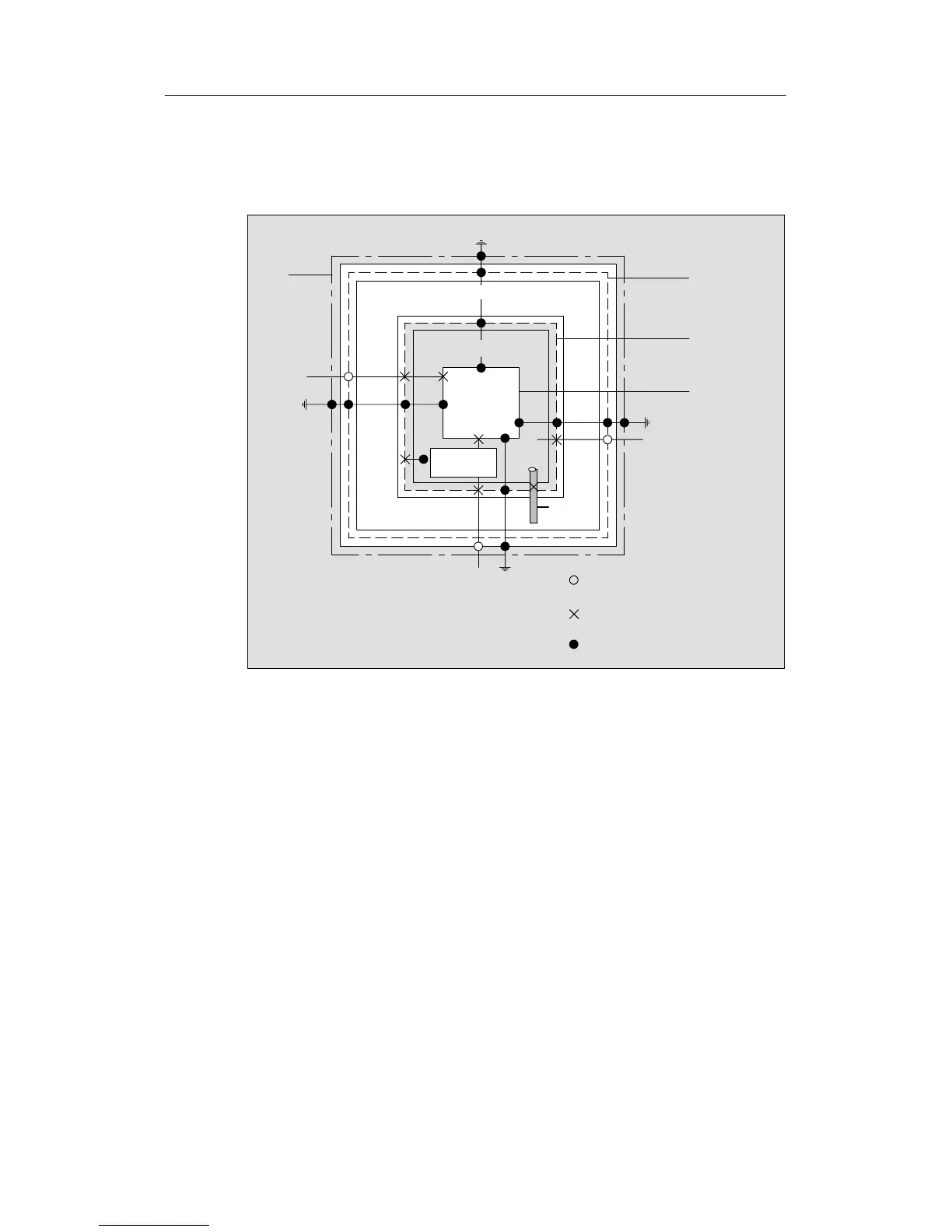
Diagram of the Lightning Protection Zones
The following diagram illustrates a lightning protection zone concept for a detached
building.
Lightning Protection Zone 0, Field Side
Lightning Protection
Lightning
Protection
Zone 3
Device
Energy-
Technical
Cable
Lightning Protection Zone 1
Building
External
Lightning
Shield
(Steel
Reinforcement)
Room Shield
(Steel
Reinforcement)
Device Shield
(Metal Housing)
Metal
Component
Non-
Electrical
Cable
Information-Technical Cable
Lightning Protection
Equipotential Bonding
Local
Equipotential Bonding
Internal
Cable
(Metal)
Galvanic
Connection
Protection
Zone 2
Figure A-6 Lightning Protection Zones of a Building
Principle of Transitions between the Lightning Protection Zones
At the transition points between the lightning protection zones, you must take
measures to prevent surges being conducted further.
The lightning protection zone concept also states that all lines at the transitions
between the lightning protection zones that can carry lightning stroke current must
be included in the lightning protection equipotential bonding.
Lines that can c arry lightning stroke current include:
• Metal pipelines (for example, water, gas and heat)
• Power cables (for example, line voltage, 24 V supply)
• Data cables (for example, bus cable).

 Loading...


