Mechanical setup of the example station
4.2 Mounting of analog module components
SM331; AI 8x12 Bit Getting Started part 1: 4 -20mA
Getting Started, 11/2006, A5E00253410-02
4-7
Positions of the measuring range modules
The position enables you to specify the transducer to be connected to the respective channel
group.
Position Type of measurement
A Thermocouple / resistance measurement
B Voltage (factory setting)
C Current (4-wire transducer)
D Current (2-wire transducer)
In our example, a sensor with a 4 to 20mA 2-wire transducer is connected to channel group
1 at input 0.
A 4-wire transducer is connected to channel group 2 at inputs 2 and 3.
Therefore, the first measuring range module should have position D and the second should
have position C.
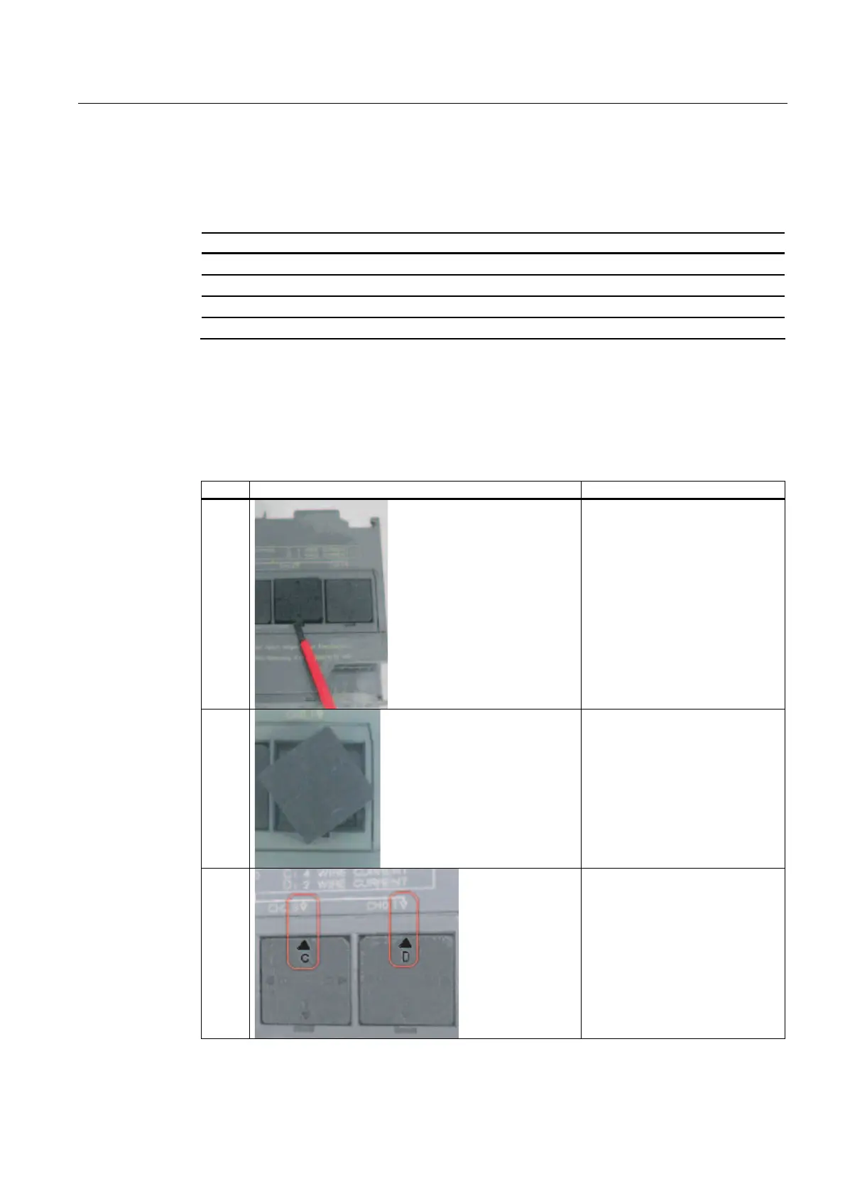
Positioning of the measuring range modules
step Graphic controller Description
1
With a screwdriver, pull out the
two measuring range modules
2
Turn the measuring range module
to the desired position:
3
Plug the measuring range module
back into the module
In our example, the module
should have the following
positions:
CH0,1: D
CH2,3: C