Electrical connection
5.3 Wiring of the analog module
SM331; AI 8x12 Bit Getting Started part 1: 4 -20mA
Getting Started, 11/2006, A5E00253410-02
5-7
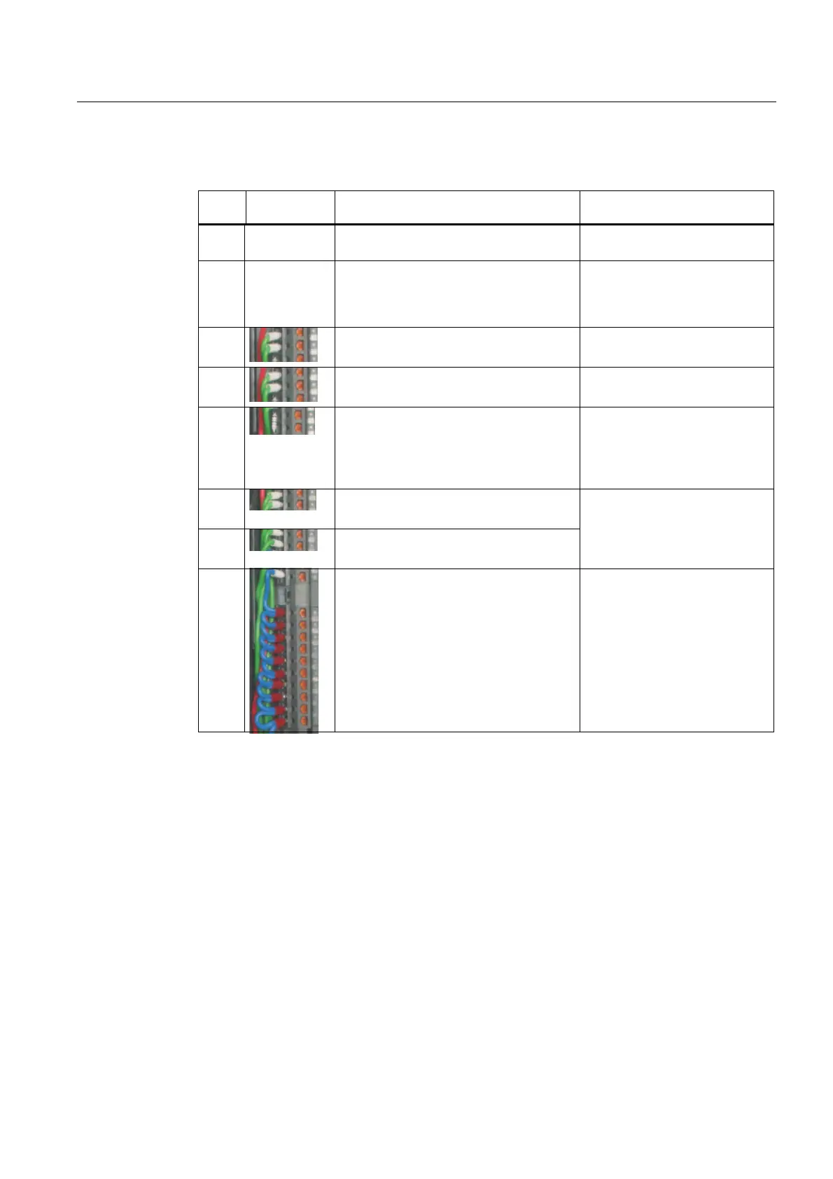
Proceed as follows
Step Graphic
controller
Connecting-up Comment
1 Open the front door of the SM331 The connection diagram is
printed on the front flap
2 Remove 6 mm of the insulation from the
ends of the wires that go into the front
connector. Attach cable end sleeves to
these ends.
3
Wire the front connector as follows:
Terminal 1: L +
Power supply of the module
4
Terminal 2: M+ sensor 1
Terminal 3: M- sensor 1
Standard wiring for 2-wire
current transducer
5
Connect terminal 4 and 5 with a 1.5 to 3.3
kΩ resistor
In order to maintain the
diagnostic capability of channel
group 0, the second unused
input must be connected to a
resistor.
6
Terminal 6: M+ sensor 2
Terminal 7: M- sensor 2
7
Terminal 8: M+ sensor 3
Terminal 9: M- sensor 3
Standard wiring for 4-wire
current transducer
8
terminal 10 (Comp) and
connect terminal 11 (M
ana
) to M
Short-circuit terminals 12 to 19 and
connect with M
ana
Terminal 20: M
For measuring current comp is
not used
Mandatory for 2-wire current
transducers
Unused channel groups should
be short-circuited with M
ana
in
order to achieve a maximum
interference resistance