The eective torque is obtained as follows:
The average motor speed is calculated as follows:
=
+
2
•
n
n n
t
0RWPLWWHO
0RWL$0RWL(
L
T
J
M
Motor moment of inertia
J
G
Gearbox moment of inertia
J
load
Load moment of inertia
n
load
Load speed
i Gear ratio
η
G
Gearbox eciency
M
load
Load torque
M
R
Frictional torque
T Cycle time
A; E Initial value, nal value in time slice Δt
i
t
e
ON duration
∆t
i
Time interval
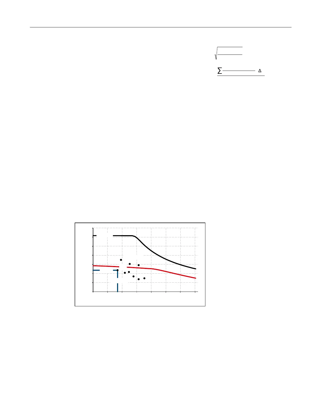
The eective torque M
e
must lie below the S1 characteristic.
The maximum torque M
max
is produced during the acceleration operation. M
max
must lie below
the voltage limiting characteristic curve. In summary, the motor is congured as follows:
7RUTXHLQ1P
0RWRUVSHHGLQUPLQ
6
0BPD[
0BPD[IURPWUDYHOFXUYH
0BUPV
QBDYHUDJH
M_max Curve of the maximum torque S1 S1 characteristic = M
0
M_e Eective torque ● Points from the traversing prole
n_mean Mean speed
Figure 5-5 Motor selection for duty cycle
You have dened the characteristic motor values corresponding to the duty cycle.
Conguration
5.2 Conguring procedure
1FK2 Synchronous Motors for SINAMICS S120
Conguration Manual, 02/2022, A5E46927724B AD 71