Configuration
5.2 Procedure when engineering
S-1FT7 synchronous motors
110 Configuration Manual, 09/2018, A5E45099423B AA
3. Definition of the load, calculation of the maximum load torque and
determination of the motor
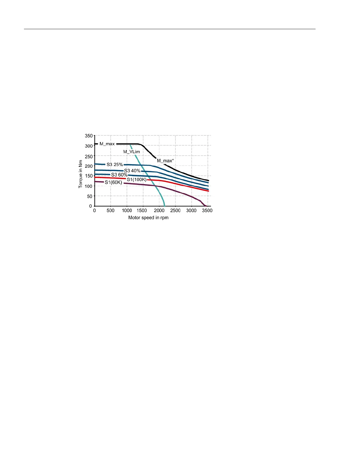
The motors are defined bases on the motor type-specific limiting characteristic curves.
The limiting characteristic curves describe the torque or power curve over the speed.
The limiting characteristic curves take the limits of the motor into account on the basis of the
DC-link voltage. The DC-link voltage is dependent on the line voltage.
In the case of torque drive the DC-link voltage is dependent on the type of Line Module and
the type of infeed module or infeed/regenerative feedback module.
Curve of the maximum torque
S3 characteristic curve for 25%
M_max* Curve of the maximum torque with field
S3 40% S3 characteristic curve for 40%
S1 (100
S1 characteristic curve at 100 K S3 60% S3 characteristic curve for 60%
S1 (60K
S1 characteristic curve for 60 K M_VLim Voltage limit characteristic without
Figure 5-1 Limiting characteristic curve for synchronous motors
1. Determine the load which is specified by the application.
Use different characteristics for the different loads.
The following operating scenarios have been defined:
– Duty cycle with constant ON duration
– Duty cycle with varying ON duration
– Free duty cycle
2. Determine the characteristic torque and speed operating points of the motor for the
defined load.