EasyManua.ls Logo

Siemens SIMOTICS S-1FT7 - PIN Assignment of the Signal Connectors

Siemens SIMOTICS S-1FT7
408 pages
To Next Page IconTo Next Page
To Previous Page IconTo Previous Page
Loading...
Electrical connection
8.3 System integration
S-1FT7 synchronous motors
Configuration Manual, 09/2018, A5E45099423B AA
393
8.3.5.3
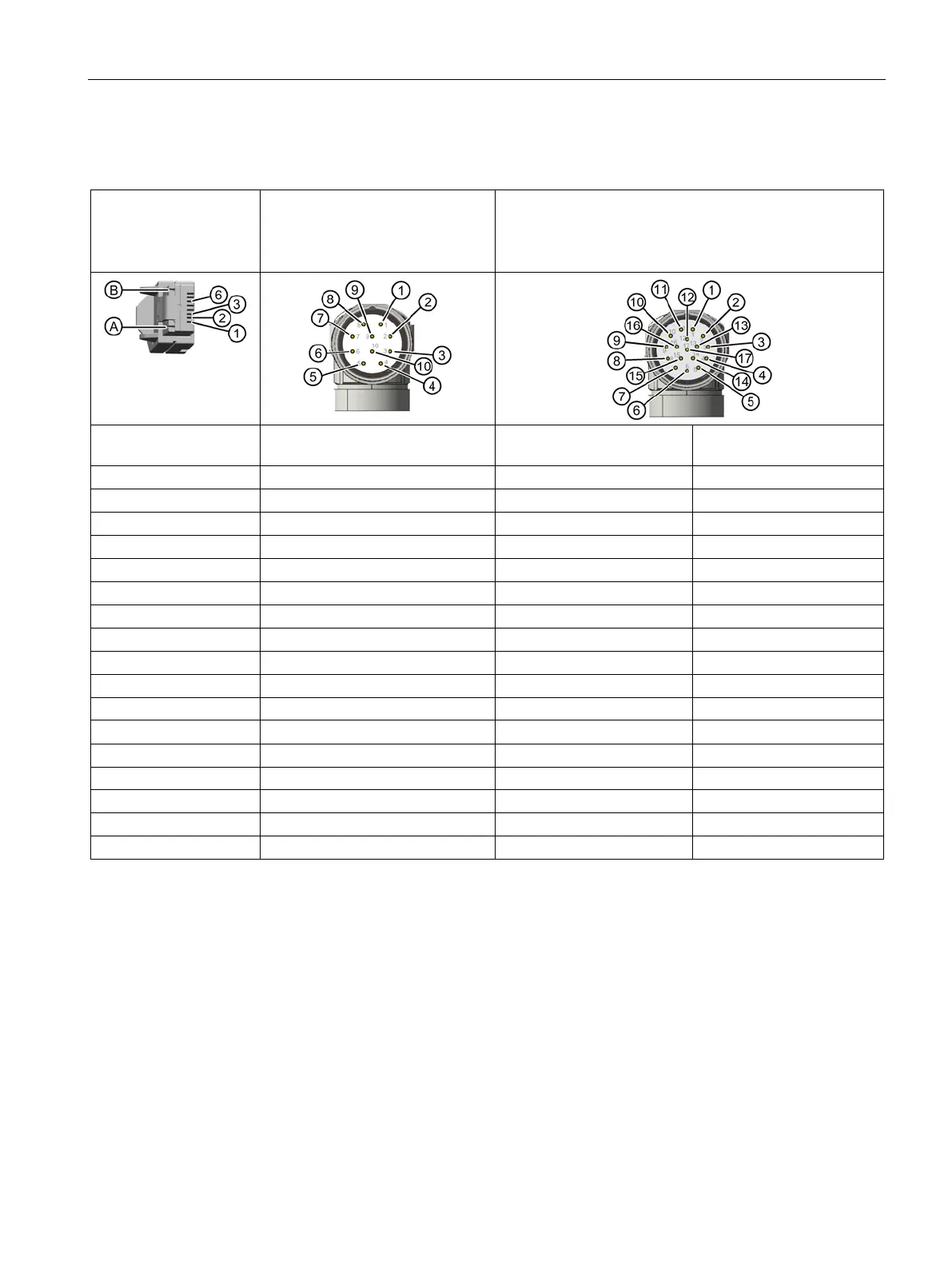
PIN assignment of the signal connectors
Pin assignment, RJ45
signal connector, with
DRIVE-CLiQ, cable
connector
Pin assignment, M17 signal con-
nector, 10-pin, with DRIVE-CLiQ,
encoder connector
Pin assignment, M23 signal connector, 17-pin, without
DRIVE-CLiQ, encoder connector
For DQI encoder with
RJ45
DQI encoder with round connector
M17
Incremental encoder sin/cos
1Vpp
Absolute encoder
sin/cos 1 Vpp
1 = TX-P
1 = TX-P
1 = Α
1 = Α
2 = TX-N
2 = TX-N
2 = A*
2 = A*
3 = RX-P
3 = not connected
3 = R
3 = data
4 = not connected
4 = not connected
4 = D*
4 = not connected
5 = not connected
5 = RX-P
5 = C
5 = clock
6 = RX-N
6 = RX-N
6 = C*
6 = not connected
7 = not connected
7 = not connected
7 = M encoder
7 = M encoder
8 = not connected
8 = not connected
8 = +1R1
8 = +1R1
A = P 24 V
9 = P 24 V
9 = -1R2
9 = -1R2
B = M 0 V
10 = M 0 V
10 = P encoder
10 = P encoder
11 = B
11 = B
12 = B*
12 = B*
13 = R*
13 = data*
14 = D 14 = clock*
15 = M sense
15 = M sense
16 = P sense 16 = P sense
17 = not connected
17 = not connected

Table of Contents

Related product manuals