Electrical connection
8.3 System integration
S-1FT7 synchronous motors
394 Configuration Manual, 09/2018, A5E45099423B AA
Signal cables
Signal cables for the motor
Use prefabricated cables to connect motors.
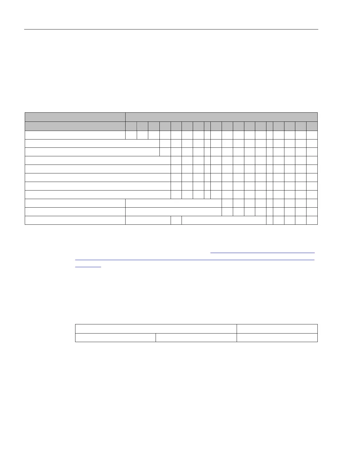
Table 8- 18 Example of the article number structure for a prefabricated cable
Position of the article number
DRIVE-CLiQ signal cable (example)
6 F X
Connectors mounted on both sides
Loosely enclosed connector for the module side
Loosely enclosed connector for the motor end 4 2
1)
1) Detailed information on the structure of the length code can be found in the catalog, see link below.
Detailed information on the signal cables is provided in Chapter "Chapter, "MOTION-
CONNECT connection systems" in Catalog D 21.4 (
https://intranet.for.siemens.com/org/i-dt-
mc/de/motion-control/support/infomaterial/kataloge/d-21-4-sinamics-s120-simotics/Seiten/d-
21-4.aspx)".
Connecting the signal cable on a force-ventilated motor
The signal connection of the force-ventilated motor is located under the fan cover or in the
intermediate flange, and cannot be seen.
The signal connection can be as shown below:
You must remove the fan cover or the intermediate flange to connect the signal cable. To
remove the fan cover or the intermediate flange when the motor is installed, you need a
minimum clearance s at the NDE.