Configuration
5.2 Procedure when engineering
S-1FT7 synchronous motors
112 Configuration Manual, 09/2018, A5E45099423B AA
1. Configure a base load for the stationary operating point. The base load torque must lie
below the S1 characteristic curve.
2. In the event of transient overloads (e.g. during acceleration), configure an overload.
Calculate the overload current in relation to the required overload torque. The overload
torque must lie below the voltage limiting characteristic curve.
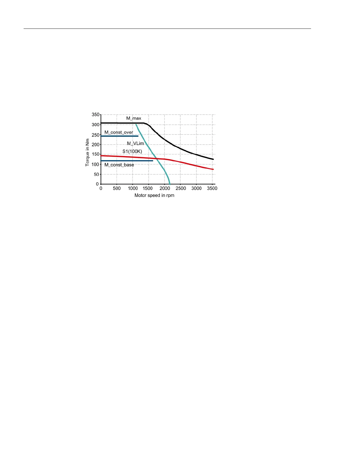
In summary, the motor is configured as follows:
M_max Curve of the maximum torque M_const_ov
Curve of the overload torque
M_VLim
Voltage limiting characteristic
M_const_ba
Curve of the base load torque
Figure 5-3 Motor selection for duty cycle with constant ON duration (example)
3. Select a motor that satisfies the requirements of duty type S1.
❒