Technical data and characteristic curves
6.1 Explanations
S-1FT7 synchronous motors
Configuration Manual, 09/2018, A5E45099423B AA
139
Calculating and determining points P1, P2, P3 and P4
n
1
= 380 V • 1000 / 87 • 0.95
2
= 4597 rpm • 290 V / 380 V
2
= 3508 rpm
limit
N
Mot
limit
limit new
= ((290 V - 261 V) / (380 V -
limit new
= 2.14 Nm
P4 is the point of intersection of M
Limit, new
and n
N
. The new voltage limiting characteristic is
obtained by connecting P2 and P4.
Enter and connect points P2 and P4.
This line is the new voltage limiting characteristic for V
Mot, new
= 290 V.
❒
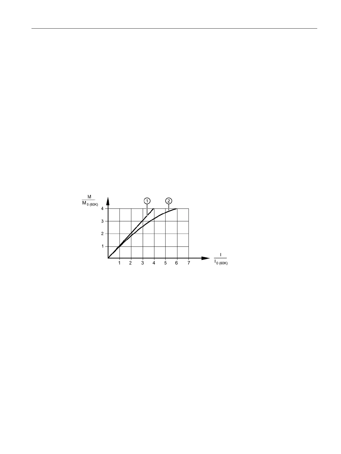
Typical M/I characteristic
Because of saturation effects, the achievable torque cannot be calculated linearly from the
current (particularly at high currents).
Figure 6-5 Torque-current characteristic curve for self-cooled motors
From M
0
(or I
0
), you can calculate the torque or the torque constant as a function of the
current using the following formulas:
T
(I) =
M
/
I
T
T
(I) = (
M
0
/
I
0
) + ((
I
-
I
0
) / (
I
max
-
I
0
)) • ((
M
max
/
I
max
) - (
M
0
/
I
0
))
0
0
max