Technical data and characteristic curves
6.2 Motor overview / assignment of Motor Modules / power cables
S-1FT7 synchronous motors
Configuration Manual, 09/2018, A5E45099423B AA
149
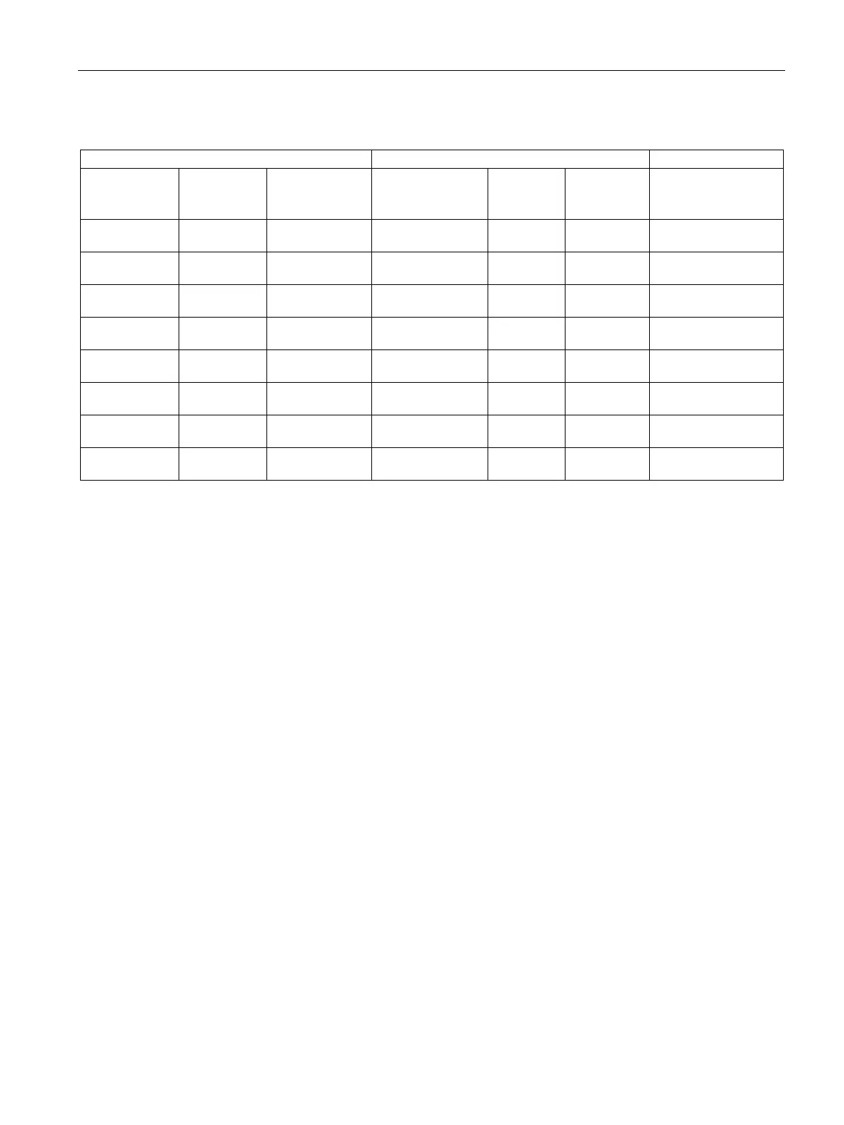
Table 6- 11 1FT7 High Dynamic water cooling
Converter: SINAMICS S120 Booksize
Connector size
5)
/
Cable cross-
section
4)
1FT7065-7WF7 19 1.5 / 4 x 2.5 6SL3120-1TE21-
18 18 6FX❑002-5❑N36-
1FT7065-7WH7 19 1.5 / 4 x 4 6SL3120-1TE23-
30 30 6FX❑002-5❑N46-
1FT7067-7WF7 25 1.5 / 4 x 4 6SL3120-1TE23-
30 30 6FX❑002-5❑N46-
1FT7067-7WH7 25 1.5 / 4 x 4 6SL3120-1TE23-
30 30 6FX❑002-5❑N46-
1FT7085-7WF7 43 1.5 / 4 x 6 6SL3120-1TE24-
45 45 6FX❑002-5❑N54-
1FT7085-7WH7 43 3 / 4 x 16 6SL3120-1TE26-
60 60 6FX❑002-5❑S23-
1FT7087-7WF7 61 3 / 4 x 16 6SL3120-1TE26-
60 60 6FX❑002-5❑S23-
1FT7087-7WH7 61 3 / 4 x 25 6SL3120-1TE28-
85 85 6FX❑002-5❑G33-
The maximum torques of servomotors up to and including stall currents of 30
A are shown
with 3-fold overload capacity. Beyond that with 2-fold.
The Motor Modules are shown as Single Motor Module (6SL3120
-1❑❑❑❑-
❑❑❑❑). Up to
and including 18
A stall current you can also choose Double Motor Modules (6SL3120-
2❑❑❑❑-❑❑❑❑). The last digit of the order number shows the version.
The 4th digit of the order number of pre
-assembled power cables defines the type (5: for
t 500 and 8: for Motion Connect 800 Plus). Via the 9th digit of the order
number the brake connection can be set (C: Without brake cores, and D: with brake
cores). The cable cross
-section for the brake connection is 2 x 1.5 mm². Power cables in
izes 1 and 1.5 are shown as SPEED-
CONNECT. For assigned Motor Modules
for IN > 30
A, the cables on the module side are equipped with ring cable lugs. From con-
nector size 3 onwards, the power connector has a full thread.
The current carrying capacity of
the power cables corresponds to EN 60204-1 for routing
type C under continuous operation conditions at an ambient air temperature of 40 °C.