Electrical connection
8.3 System integration
S-1FT7 synchronous motors
Configuration Manual, 09/2018, A5E45099423B AA
375
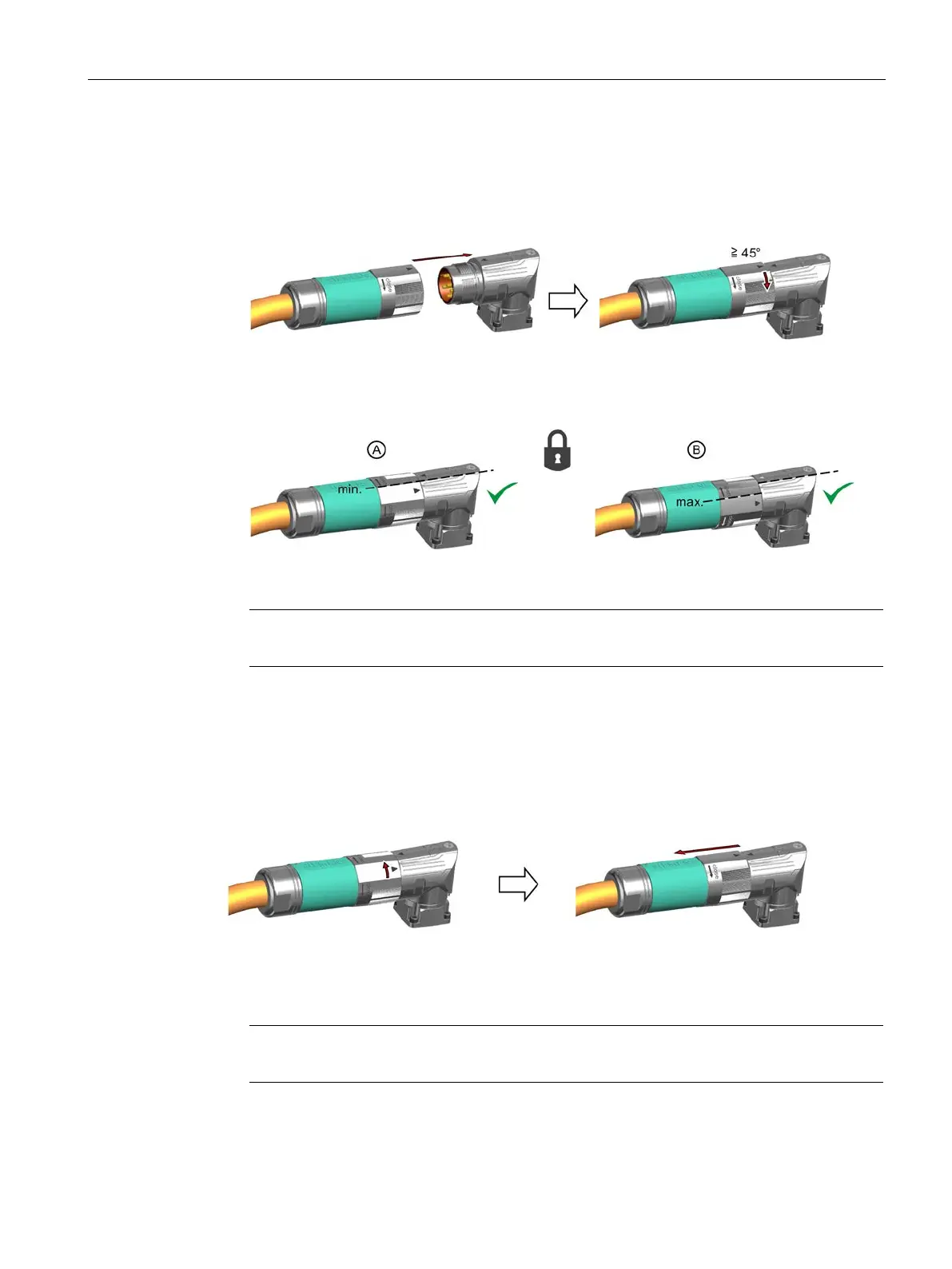
1. Ensure that the union nut of the SPEED-CONNECT connector is rotated to the end stop
in the direction of the "open" arrow.
2. Align the SPEED-CONNECT connector so that the triangles on the top of the connectors
are opposite one another.
3. Push the power connector onto the motor connecting socket as far as it will go.
4. Turn the union nut by hand in the direction of "close" through at least 45° (position A) or
up to the end stop (position B)
Maximum locking up to the end stop
Note
A secure connection is only guaranteed from positio
n A onward.
You have established a secure connection.
❒
Releasing a SPEED-CONNECT connection
Procedure
1. Turn the union nut of the SPEED-CONNECT connector in the direction of "open" to the
end stop. The triangles on the top of the connectors must be opposite one another.
2. Withdraw the connector.
Note
Pull out the connector at the connector itself, do not pull on the cable.
You have disconnected the SPEED-CONNECT connection.
❒