Electrical connection
8.3 System integration
S-1FT7 synchronous motors
388 Configuration Manual, 09/2018, A5E45099423B AA
The motor holding brake requires 24 V ± 10 % at the motor connection in order to reliably
open.
● Take into account the voltage drops along the supply cable.
● Use a Control Supply Module (CSM) or a regulated DC power supply, whose setpoint is
set to 26 V.
● Use power supply cables with a minimum cross-section of 1.5 mm².
● Calculate the maximum permissible cable length using the following formula.
If the maximum voltage of 24 V DC +10 % is exceeded, then the brake can close again.
You can approximately calculate the voltage drop Δ
U
for copper cables as follows:
Δ
U
/ V = 0.042 •
x
•
I
Brake
=
l
/
q
/ mm
2
= brake conductor cross-section
Brake
Note
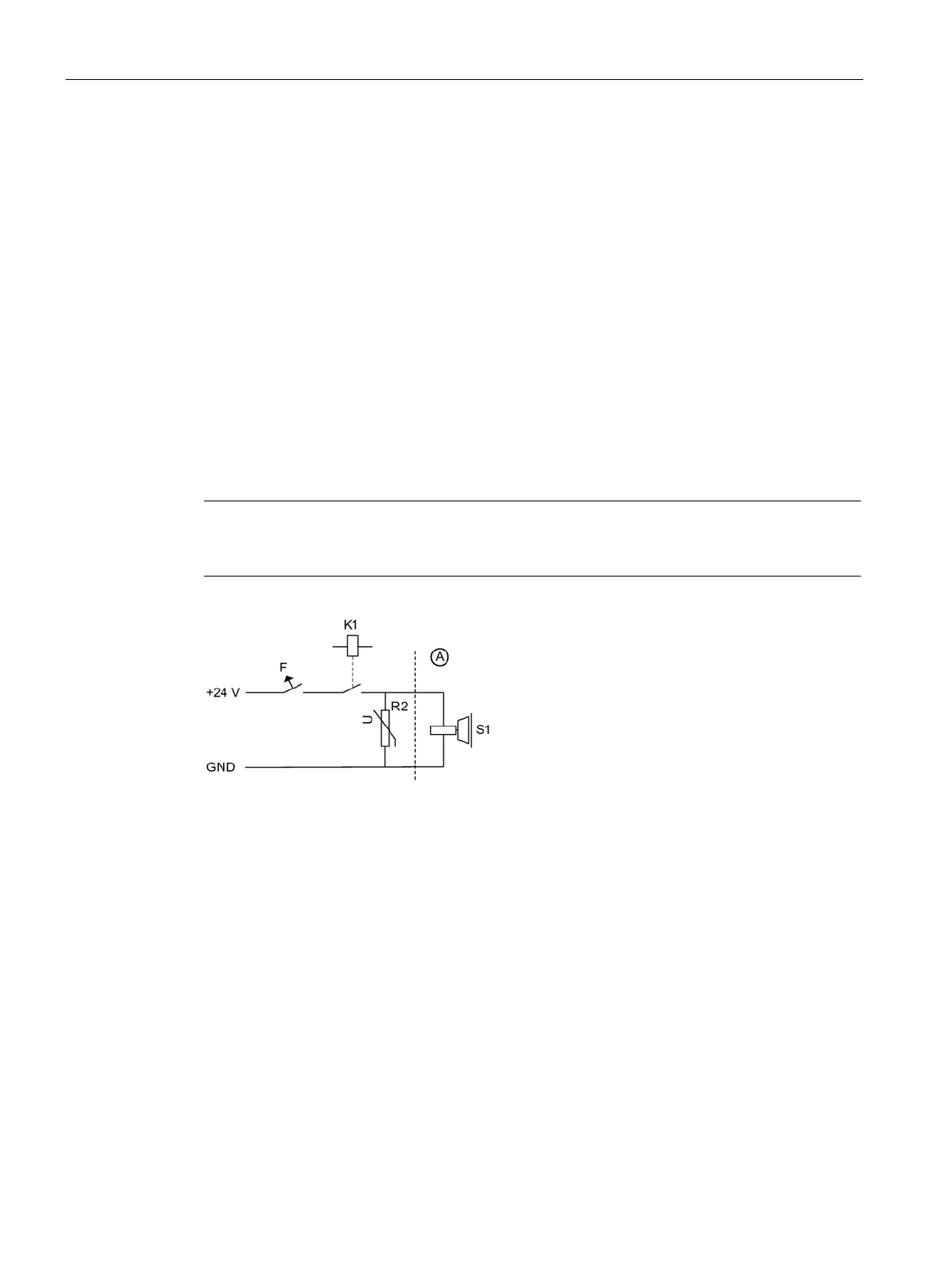
Integrate a protective circuit into the incoming cable. In this way, you avoid
switching
overvoltages and possible influence of the installation environment. See the figure below
Figure 8-9 Suggested circuit for the external power supply with protective circuit