Mechanical properties
3.1 Cooling
S-1FT7 synchronous motors
Configuration Manual, 09/2018, A5E45099423B AA
45
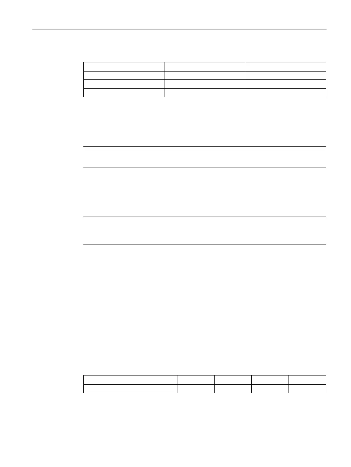
Table 3- 7 Pressure drop at the nominal coolant flow
1FT708x 4 l/min 0.03 MPa
Ensure the nominal coolant flows in the above table for sufficient heat dissipation.
If various components are connected up in the cooling circuit, it may be necessary to
measure the inlet and outlet pressure and adjust accordingly.
Note
Mount flow restrictors on the cooling water outlet of the motor or the relevant component!
● Adjust the pressure, if necessary.
Cooling water inlet temperature
The motors are designed for operation with a cooling water inlet temperature of ≤ 30 °C.
Note
Cooling water temperatures that are lower than the ambient temperature tend to result in
increased water condensation.
● Use the formula below to determine the permissible cooling water inlet temperature to
prevent condensation from forming on the motor surface:
T
cooling water
>
T
ambient
- 5 K
The determined temperature
T
cooling water
is valid for a relative humidity up to approximately
75%.
The cooling water inlet temperature must be higher if the relative humidity is > 75%.
The cooling water inlet temperature can be lowered if the relative humidity is < 75%.
If necessary, a Mollier diagram can be used to determine more precise details.
The permissible rated torque M
N
of the motor changes at a cooling water inlet temperature of
≥ 30 °C.
● Reduce the static torque M
0
according to the derating factor k in the following table.
Table 3- 8 Derating factors
Cooling water inlet temperature
Reduce the torque and the speed by the derating factor.
You can calculate the reduced rated torque
M
N red
with the following formula:
M
N red
= M
N
-
(
M
0
-
M
0
*
k
)