4 Operating the Application
4.3 Monitoring and parameter access via operator panel
SINAMICS G120 DP at S7-1200
Entry-ID: 70155469, V1.4, 07/2018
Copyright Siemens AG 2018 All rights reserved
Start the write or read job with the
“Start Transfer” button.
Note:
After a write job the new data is
adopted as read parameters in the
white fields in the left part of the
screen. After writing you need not
trigger any additional read job for the
update.
The job status specifies how the job was
completed:
Job completed successfully
without error
The job was transferred without
errors, however, it could not be
realized in SINAMICS (e.g., a
negative time was given)
For fault diagnostics see /1/.
Terminate the write or read job by
clicking “Terminate Transfer”
The job status bits are deleted
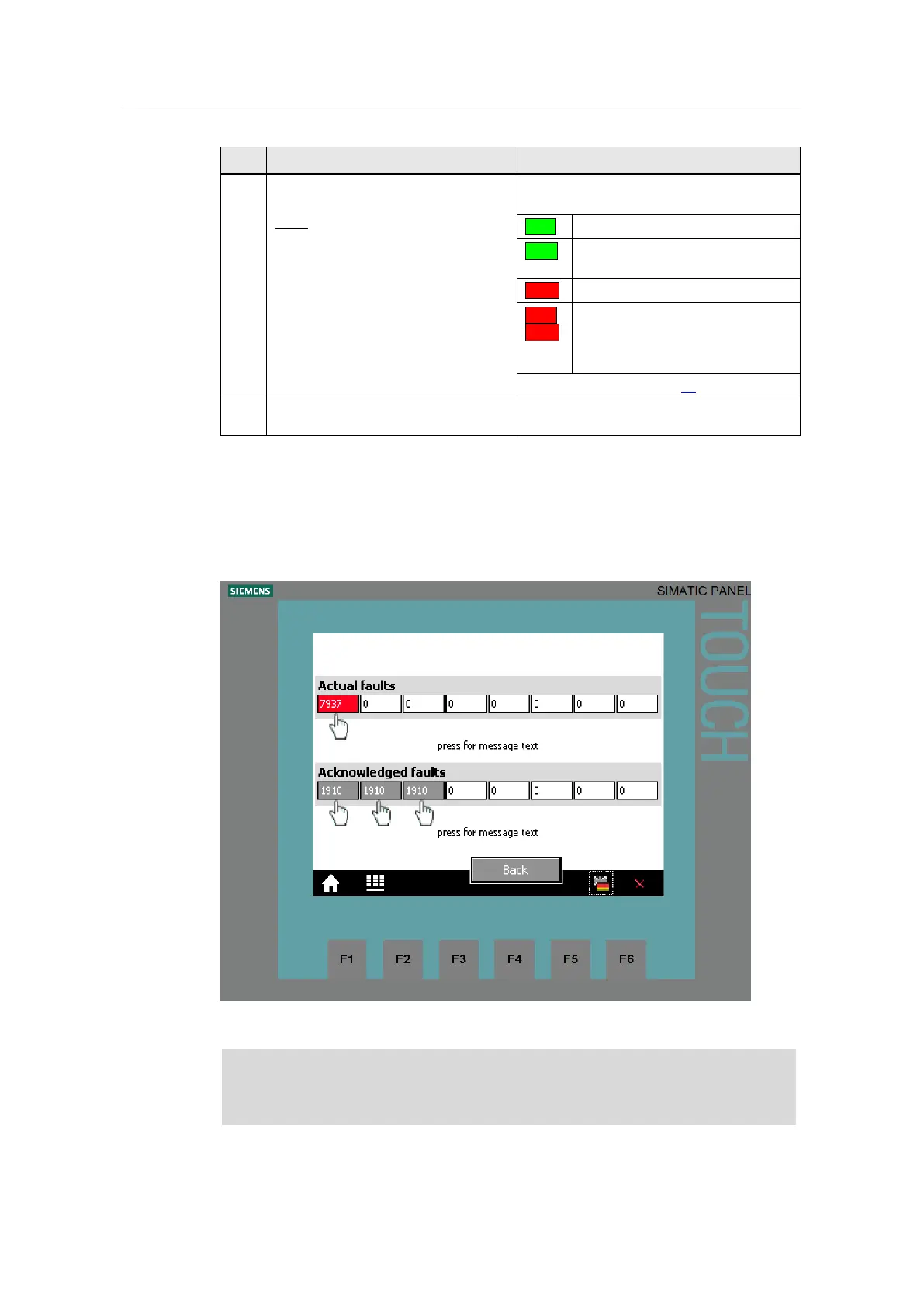
Fault buffer
The screen displays the fault codes of eight current and eight acknowledged faults,
which are saved in the SINAMICS converter.
Figure 4-7: Display of fault buffer
The fault codes in the above screen correspond to control tags V_3_Value_00
(DW18) to V_3_Value_15 (DW48) in the “answer_from_drive” data block (DB103).
The fault butters are only updated when you trigger an acyclic transmission. In
the example object, you execute the “Read parameters” function before
switching to the display of the fault buffer.
Tap or click on the message number to display the respective text.

 Loading...


