5 Functional Mechanisms of this Application
5.2 Parameter access functionality
SINAMICS G120 DP at S7-1200
Entry-ID: 70155469, V1.4, 07/2018
Siemens AG 2018 All rights reserved
Structure
FB “Parameter” consists of two parts:
A step sequence which controls the sequence of the parameter access
(networks 1 to 22).
The calls of the system functions “Write data set” or
“Read data set” (networks 23 to 25).
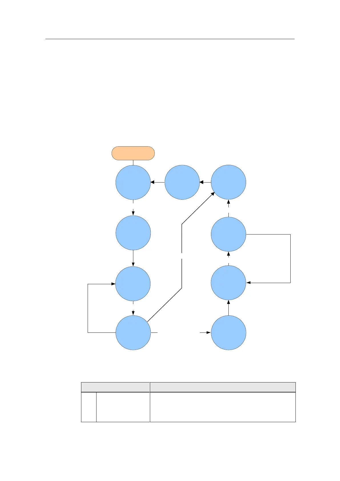
Step sequence
The individual steps of FB “Parameters” are represented in the following graphic.
The possible transitions between the individual steps are also displayed there.
Figure 5-12 Step sequence
0
Wait for start
trigger
1
Start WRREC
2
Wait for end
of WRREC
5
Wait for end
of RDREC
6
Check result
of RDREC
7
Check for
errors, copy
output
3
Check result
of WRREC
4
Start RDREC
START
8
Finalize job
other faults
rising START signal
sending finished
not ready fault
sending successful
receiving finished
not ready fault
other faults
In the individual states of the step sequence, the following functions are executed:
Table 5-4: Function of the states of FB “Parameters”
If START is false, all the transmission-related, block-
internal signals and output signals are deleted.
It is waited for a rising edge of the “Start” signal.
If it is detected, “busy” will be set and step 1 activated.

 Loading...


