Mechanical installation
3.2 Mounting in a control cabinet
SINAMICS V20 Converter
24 Operating Instructions, 10/2019, A5E34559884-012
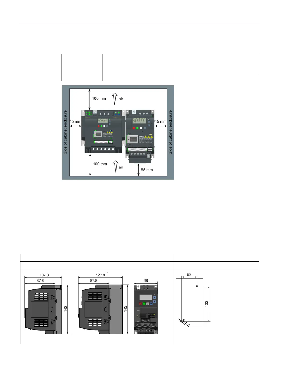
Mounting clearance
Bottom ≥100 mm (for frame sizes AA ... AD, B ... E, and frame size A without fan)
≥ 85 mm (for fan-cooled frame size A)
3.2 Mounting in a control cabinet
You can mount the converter directly on the surface of the mounting panel in a suitable
control cabinet.
Two additional mounting methods are also available for different frame sizes. For more
information, refer to the following sections:
● Push-through mounting (frame sizes B ... E) (Page 29)
● DIN rail mounting (frame sizes AA, AB, AC, A, and B) (Page 32)
Outline dimensions and drill patterns
1)
Fixings: 2 x M4 screws, nuts, washers
Tightening torque: 1.8 Nm ± 10%

 Loading...


