Mechanical installation
3.4 Push-through mounting (frame sizes B ... E)
SINAMICS V20 Converter
Operating Instructions, 10/2019, A5E34559884-012
29
3.4 Push-through mounting (frame sizes B ... E)
The frame sizes B to E are designed to be compatible with "push-through" applications,
allowing you to mount the heatsink of the converter through the back of the cabinet panel.
When the converter is mounted as the push-through variant, no higher IP rating is achieved.
Make sure that the required IP rating for the enclosure is maintained.
Two additional mounting methods are also available for different frame sizes. For more
information, refer to the following sections:
● Mounting in a control cabinet (Page 24)
● DIN rail mounting (frame sizes AA, AB, AC, A, and B) (Page 32)
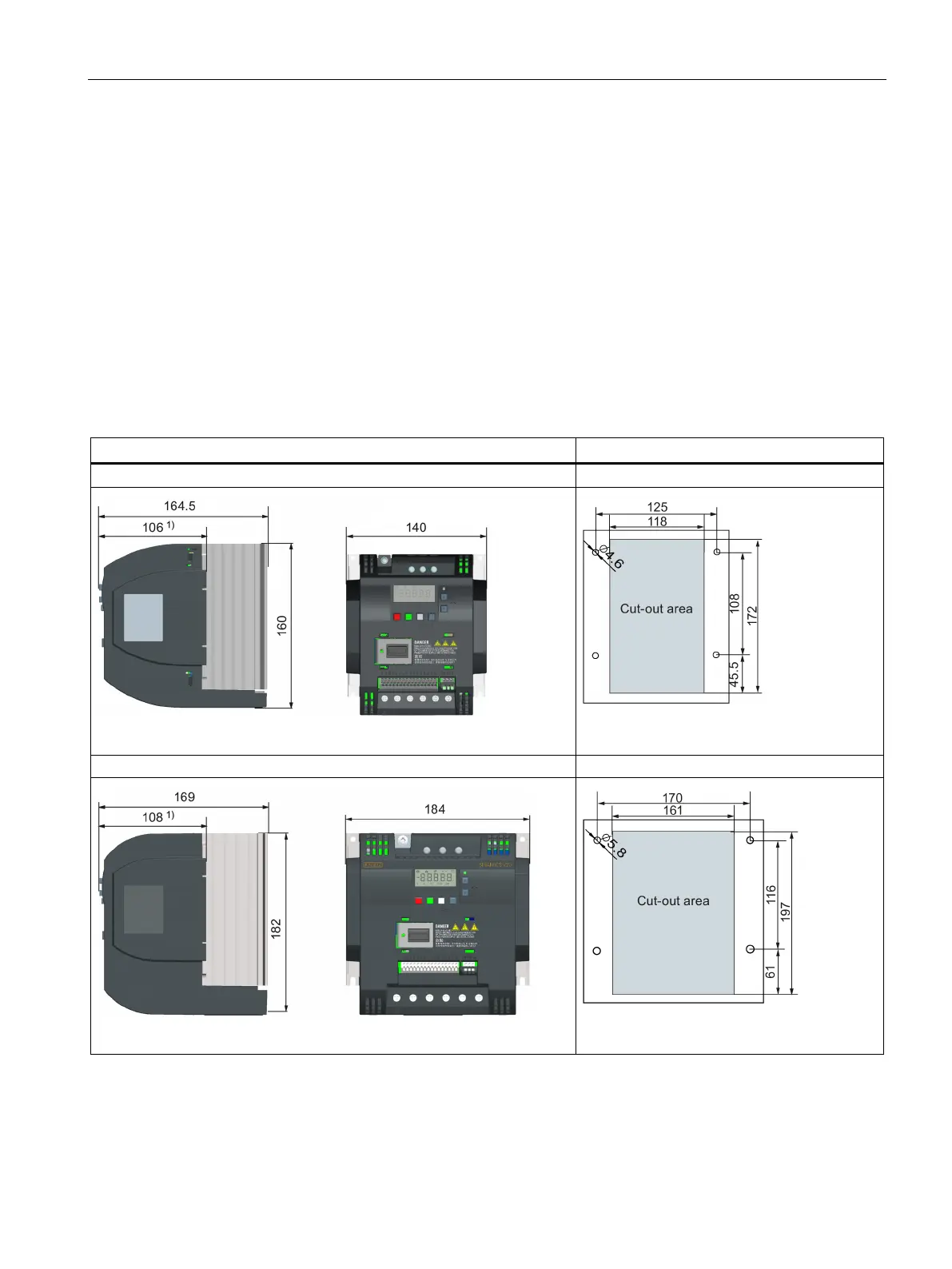
Outline dimensions, drill patterns, and cut-outs
Drill pattern and cut-out (mm)
Fixings: 4 x M4 screws
Tightening torque: 1.8 Nm ± 10%
Fixings: 4 x M5 screws
Tightening torque: 2.5 Nm ± 10%

 Loading...


