Commissioning via the built-in BOP
5.1 The built-in Basic Operator Panel (BOP)
SINAMICS V20 Converter
Operating Instructions, 10/2019, A5E34559884-012
57
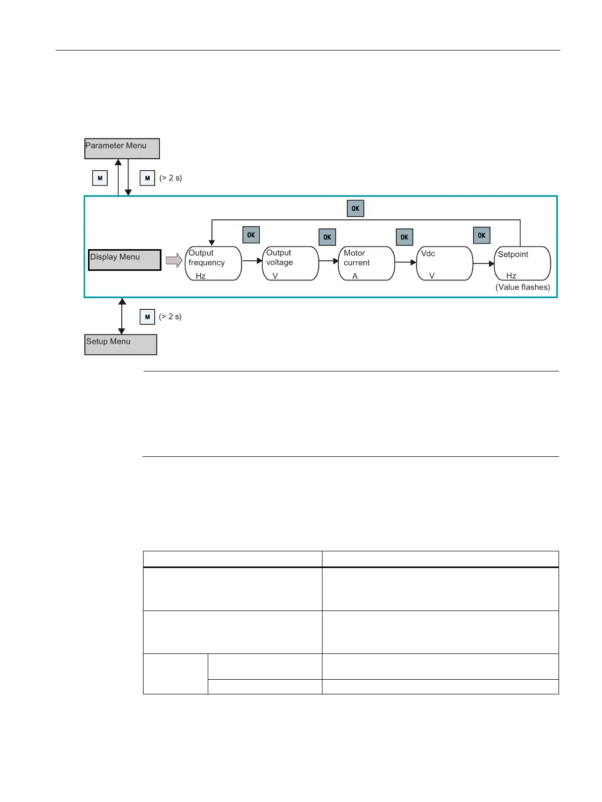
5.1.3 Viewing converter status
The display menu provides a basic monitoring view of some key parameters such as
frequency, voltage, current, and so on.
If you have set P0005 to a non-zero value which represents the parameter number
selected in P0005, then the converter displays the value of the selected parameter in the
display menu by default. For more information about normal editing of parameters, see
Section "Editing parameters (Page 57)".
For more information about the display menu structure with active faults, see Section
"Faults (Page 333)".
5.1.4 Editing parameters
This section describes how to edit the parameters.
Parameter types
CDS-dependent parameters
• Dependent on Command Data Set (CDS)
• Always indexed with [0...2] *
• Available for CDS switching via P0810 and P0811
DDS-dependent parameters
• Dependent on Drive Data Set (DDS)
• Always indexed with [0...2]
• Available for DDS switching via P0820 and P0821
Other param-
eters
Multi-indexed parameters These parameters are indexed with the range of indices
dependent on the individual parameter.
These parameters are not indexed.
-dependent parameter has only one default value, despite of their three indices.
Exception: By default, P1076[0] and P1076[2] are set to 1 while P1076[1] is set to 0.

 Loading...


