Transformations
7.8 Kinematic transformation
Job planning
7-58 Programming Manual, 03/2006 Edition, 6FC5398-2BP10-1BA0
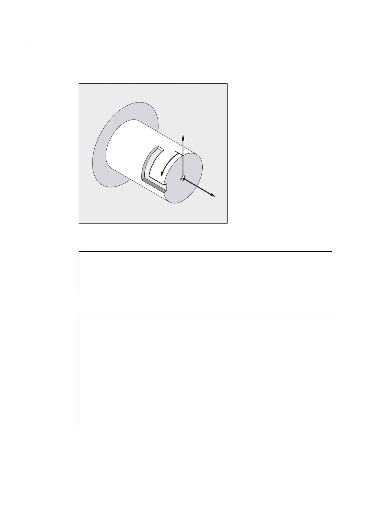
Example of making a hook-shaped groove:
=
<
;
Activate cylinder surface transformation
N10 T1 D1 G54 G90 F5000 G94 ;Tool selection, clamping compensation
N20 SPOS=0
N30 G0 X25 Y0 Z105 CC=200
;Approach start position
N40 TRACYL (40) ;Enable cylinder peripheral curve
;transformation
N50 G19 ;Plane selection
Making a hook-shaped groove
N60 G1 X20 ;Infeed tool to groove base
N70 OFFN=12 ;Define 12 mm groove side spacing
;relative to groove center line
N80 G1 Z100 G42 ;Approach right side of groove
N90 G1 Z50 ;Groove cut parallel to cylinder axis
N100 G1 Y10 ;Groove cut parallel to circumference
N110 OFFN=4 G42 ;Approach left side of the groove;
;define 4 mm groove side spacing
;relative to the groove center line
N120 G1 Y70 ;Groove cut parallel to circumference
N130 G1 Z100 ;Groove cut parallel to cylinder axis
N140 G1 Z105 G40 ;Retract from groove wall
N150 G1 X25 ;Move clear
N160 TRAFOOF
N170 G0 X25 Y0 Z105 CC=200 ;Approach start position
N180 M30

 Loading...


