12.95
4.2 Interfaces of the SINUMERIK 810D
4-61
E Siemens AG, 2002. All rights reserved
SINUMERIK 810D Manual Hardware Configuration (PHC) -- 11.02 Edition
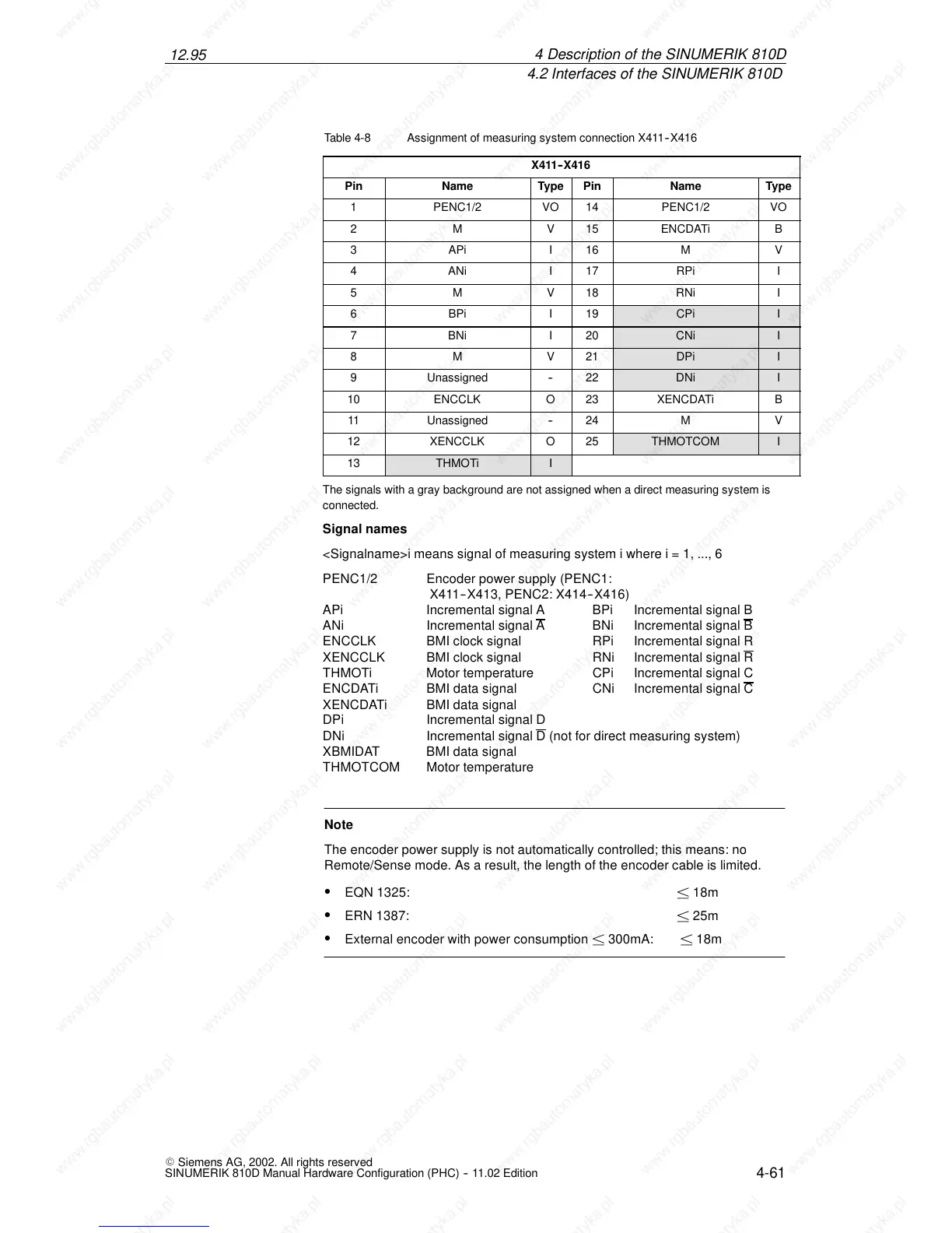
Table 4-8 Assignment of measuring system connection X411--X416
X411--X416
Pin Name Type Pin Name Type
1 PENC1/2 VO 14 PENC1/2 VO
2 M V 15 ENCDATi B
3 APi I 16 M V
4 ANi I 17 RPi I
5 M V 18 RNi I
6 BPi I 19 CPi I
7 BNi I 20 CNi I
8 M V 21 DPi I
9 Unassigned -- 22 DNi I
10 ENCCLK O 23 XENCDATi B
11 Unassigned -- 24 M V
12 XENCCLK O 25 THMOTCOM I
13 THMOTi I
The signals with a gray background are not assigned when a direct measuring system is
connected.
Signal names
<Signalname>i means signal of measuring system i where i = 1, ..., 6
PENC1/2 Encoder power supply (PENC1:
X411--X413, PENC2: X414 --X416)
APi Incremental signal A BPi Incremental signal B
ANi Incremental signal A
BNi Incremental signal B
ENCCLK BMI clock signal RPi Incremental signal R
XENCCLK BMI clock signal RNi Incremental signal R
THMOTi Motor temperature CPi Incremental signal C
ENCDATi BMI data signal CNi Incremental signal C
XENCDATi BMI data signal
DPi Incremental signal D
DNi Incremental signal D
(not for direct measuring system)
XBMIDAT BMI data signal
THMOTCOM Motor temperature
Note
The encoder power supply is not automatically controlled; this means: no
Remote/Sense mode. As a result, the length of the encoder cable is limited.
S EQN 1325: ± 18m
S ERN 1387: ± 25m
S External encoder with power consumption ± 300mA: ± 18m
4De

 Loading...


