12.95
4.2 Interfaces of the SINUMERIK 810D
4-63
E Siemens AG, 2002. All rights reserved
SINUMERIK 810D Manual Hardware Configuration (PHC) -- 11.02 Edition
The position of the operating and display elements on the front panel of the
CCU1/2 is shown in Fig. 4-1.
Table 4-10 Operating and display elements on the CCU1/2 module
Desi-
gnation
Type Meaning
RE-
SET(S1)
Button
Triggers a hardware RESET for resetting the control and drive
and subsequent full bootup.
S3
Rotary
switch
NCK start-up switch
Position 0: Normal operation
Position 1: General NCK reset
Position 2: NCK software update from memory card
Positions 3 -- 7: Reserved
S4
Rotary
switch
PLC mode selector switch
Position 0: PLC RUN
Position 1: PLC RUN P
Position 2: PLC STOP
Position 3: MRES
LEDs
(left row)
green LED
red LED
red LED
yellow LED
+5V: Lights up when the supply voltage
is within the tolerance range.
NF: Lights up when the NCK or the PLC watchdog
has responded
SF: Lights up whenever drive errors occur. Goes out after
the system is booted in error--free condition.
CB: Lights up when data transfer
takes place over the MPI interface.
LEDs
(right
row)
green LED
red LED red
LED
yellow LED
yellow LED
PR: PLC-RUN status
PS: PLC-STOP status
PF: Lights up if a PLC error occurs
PFO: PLC FORCE status
-- : Not used (lights up briefly on reset)
H3 7--segment
Software-supported output of test and
error messages
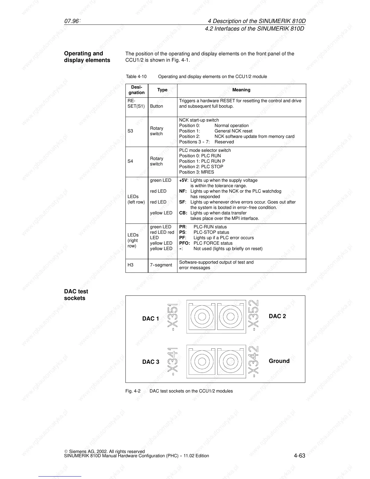
DAC 1
DAC 3
DAC 2
Ground
Fig. 4-2 DAC test sockets on the CCU1/2 modules
Operating and
display elements
DAC test
sockets
4De

 Loading...


