Project Planning Manual SIPART DR20
Planning example S2
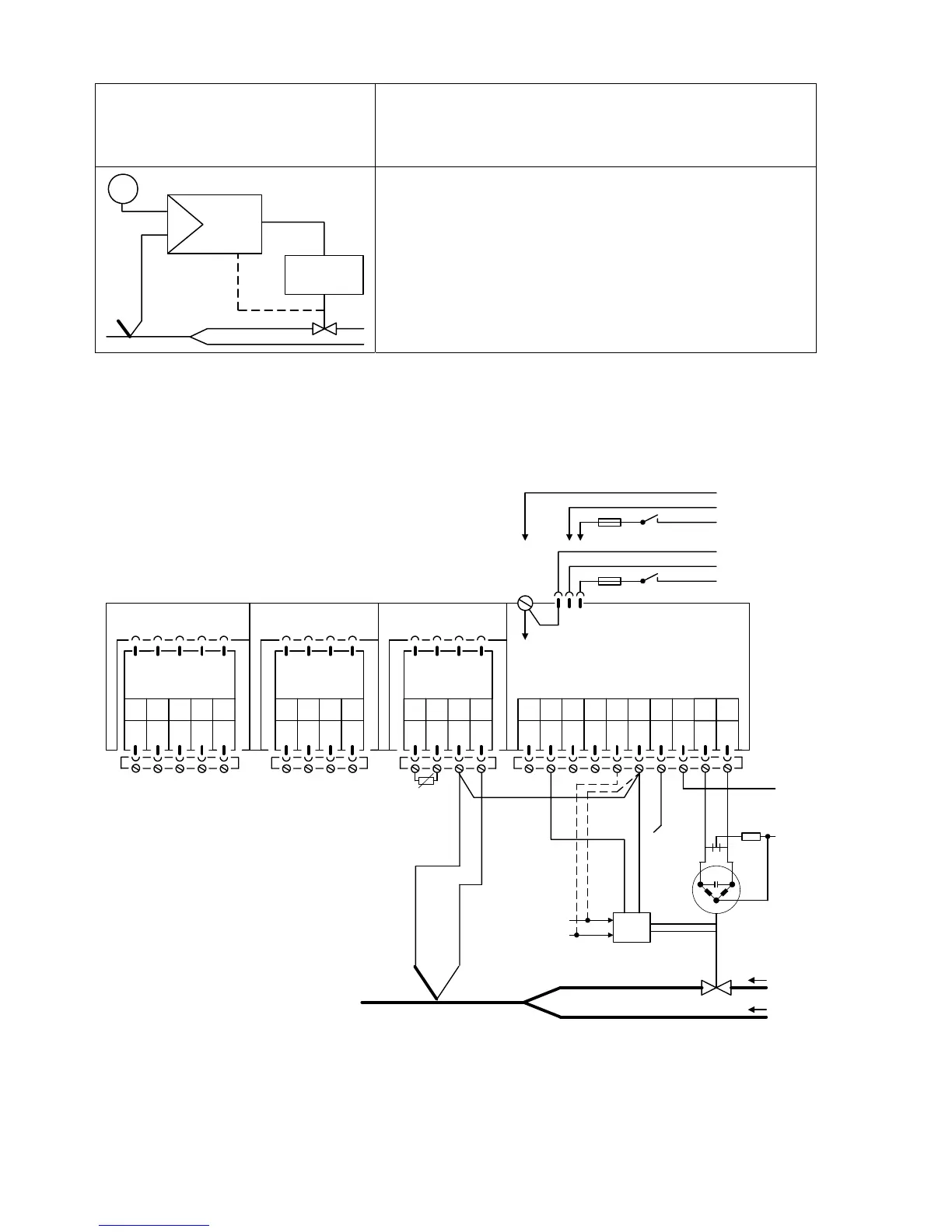
Fixed setpoint control, controlled variable direct from
thermocouple (internal cold junction), position feedback
from electronic position transmitter (EPT)
W
X
y
Drive
Y
R
The controlled variable from the thermocouple is applied to
the analog input AE3. The measuring range is
programmable. The controlled variable must be linearized
(see setting instructions on page 76 and 89).
The position feedback from the EPT is applied to input
AE2. The input signal range is 0 to 20 mA.
The alarm circuit monitors the controlled variable
(temperature) (set parameters A2 = min. and A1 = max.).
Please refer to the remarks on page 108 and the note on page 15 !
Setting of configuring switches: S2 = 2 or 3, S8 = 1, S14 = 1, S22 = 1, S32 = 1
AE1 AE2 BE BA L+ GND GND L
12345678
SIPART DR20 S
6DR2001-1 (AC 230 V)
6DR2001-2 (AC 115 V)
6DR2001-4 (UC 24 V)
123412341234
PE
N
L
AC 115 V
AC 230 V
⎫
⎬
⎭
PE
N
UC 24 V
L
⎫
⎬
⎭
Slot 3 GW Slot 2 AE4 Slot 1 AE3
-
∆
y+
∆
y
910
5
M1 A1 R1 A2 M2
not equipped
Option module
6DR2801-8A
M M/A S E
L
N
+-
Option module
6DR2800-8T
EPT
+
-
+
-
R
comp
y
R
X
126

 Loading...


