Project Planning Manual SIPART DR20
Planning example S7
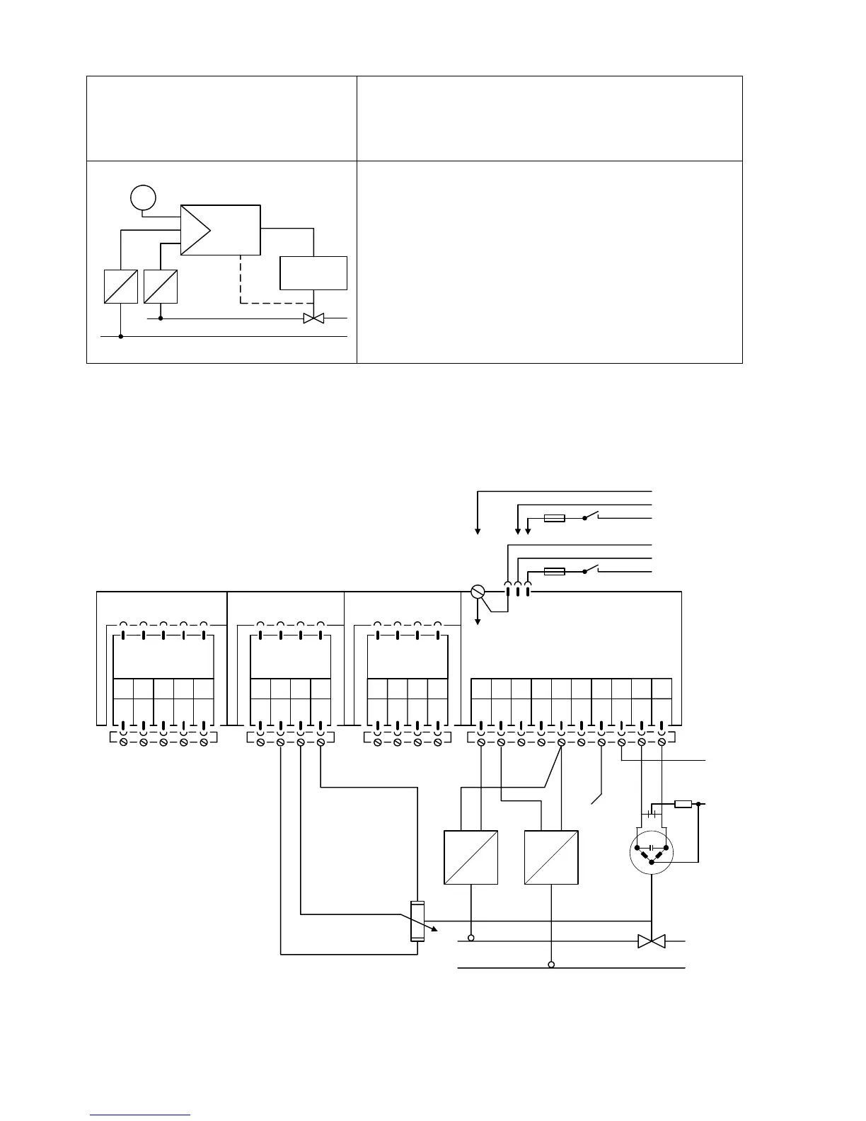
Ratio control, controlled variable (x1) and command
variable (x2) applied to controller from two-wire
transmitters
W
X
2
y
Drive
X
1
Y
R
The controlled variable x from the transmitter is applied
to analog input AE1, the position feedback from the
electronic position transmitter is applied to analog input
AE2 of the controller. The transmitter is powered via the
same lines. The input signal range of the controller is 4
to 20 mA.
Feedback of final control element position via resistance
transmitter to AE4.
The alarm circuit monitors the negative deviation xd for
max. / min. deviations (set parameters A2 and A1 !).
Please refer to the remarks on page 108 and the note on page 15 !
Setting of configuring switches: S1 = 7, S2 = 2, S4 = 1, S5 = 1, S9 = 1, S10 = -1, S22 = 1, S32 = 1
AE1 AE2 BE BA L+ GND GND L
12345678
SIPART DR20 S
6DR2001-1 (AC 230 V)
6DR2001-2 (AC 115 V)
6DR2001-4 (UC 24 V)
123412341234
PE
N
L
AC 115 V
AC 230 V
⎫
⎬
⎭
PE
N
UC 24 V
L
⎫
⎬
⎭
Slot 3 GW Slot 2 AE4 Slot 1 AE3
-
∆
y+
∆
y
910
5
M1 A1 R1 A2 M2
Option module
6DR2801-8R
The supply voltage present at the transmitters
is 15 V in the most unfavourable cases !
not equipped !
Option module
6DR2801-8A
M M/A S E
L
N
II
R
E
R
A
S
R = R
A
+
∆
R + R
E
132

 Loading...


