Technical specifications
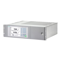
11.2 Technical specifications of rack-mounted housing
120
Quick Start
Compact Operating Instructions, 05/2018, A5E31805656-06
Electrical characteristics
EMC interference
immunity (electro-
magnetic compati-
bility) during
operation:
with one and/or two
OXYMAT 7 /
in accordance with the standard requirements of
NAMUR NE21 (05/2006) and EN 61326-1 (2013)
with one or two
CALOMAT 7 units
in accordance with the standard requirements
NAMUR NE21 (05/2006) and EN 61000-6-
No
in accordance with EN 61010-1, overvoltage category II
Power unit cable
• Cable diameter: max. diam. 10 mm
2
• Core cross-section: max. 3 x 2.1 mm
2
Table 11- 3 Rack-mounted enclosure: Electrical inputs and outputs
Electrical inputs and outputs
Digital outputs (DO) 8, with changeover contacts, parameters can be freely
assigned, e.g. for measuring range identification; max. load:
24 V AC/DC/1.7 A (total load for all 8 relay outputs in con-
tinuous operation max. 160 W), floating, non-sparking
Digital inputs (DI) 8, designed for 24 V, isolated, freely parameterizable, e.g.
Service interface (front)
Table 11- 4 Rack-mounted enclosure: Option modules
Option module 1.1
• 12 digital outputs, with changeover contacts, max. load: 24 V
AC/DC / 1.7 A
(total load for all 12 relay outputs in continuous operation
max. 244 W), floating, non-sparking
• 8 digital inputs, designed for 24 V, floating, freely configurable
Option module 2.1
• 6 analog outputs, 0/4 to 20 mA, floating; maximum load:
R
L
≤ 750 Ω
• 6 digital outputs, load rating: 24 V AC/DC/1.7 A (total load for
all 6 relay outputs in continuous operation max. 122 W), float-
ing, non-sparking
Option module 2.2
• 6 analog outputs, 0/4 to 20 mA, floating; maximum load:
R
L
≤ 750 Ω
• 4 analog inputs 0/4 to 20 mA, non-isolated, internal re-
sistance ≤ 100 Ω
• 4 digital inputs, designed for 24 V, floating

 Loading...


