Note
When leaving bypass mode, the purging unit F870S returns to the same mode it was in
previously (pre-purging phase or purging phase).
B.1.1.2 Ex p safety equipment
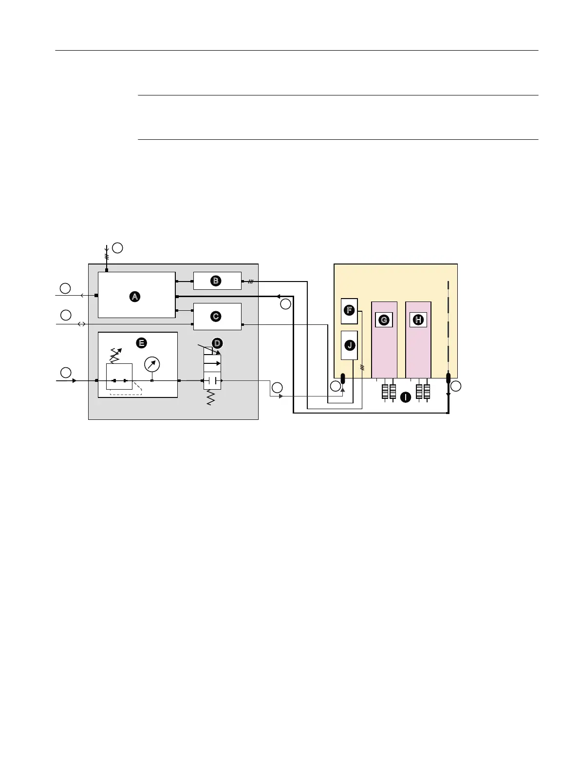
Pneumatic and electric connections of the Ex p control system (example)
%
$
&
(
'
)
-
*
+
,
6,352&(66
*$
)6
A Ex p controller F870S F Power connection
B Ex power relay SR853 G Analyzer module 1 (AM1)
C Ex interface relay SR852, 16-pin H Analyzer module 2 (AM2)
D Proportional valve I Flame arrestors
E Pressure regulating valve for purg‐
ing gas with gauge
J Signal cable connection
① Power connection
② Purging gas connection to the Ex p controller F870S, 12mm (0.47″) (outer diameter)
③ Purging gas inlet
④ Purging gas outlet
⑤ Purging gas connection from Ex p controller F870S, 12mm (0.47″) (outer diameter)
⑥ Purging gas connection; supply pressure 1000 hPa (rel.)
⑦ Connection from and to Ex interface relay SR852
⑧ Exhaust air outlet. If appropriate connection of a 1" line, max. length 20 m
FigureB-2 Gas path of the Exp safety equipment, Gönnheimer ElektronikGmbH
Connection information
The supply pressure has to be suciently large (2.5 ... 5 bar).
Ex px safety equipment
B.1Overview
SIPROCESS GA700 rack and wall mounted devices
Compact Operating Instructions, 06/2023, A5E35134047-AB 109

 Loading...


