4.6 Connecting the rack-mounted device
4.6.1 Arrangement of the gas connections in the rack-mounted device
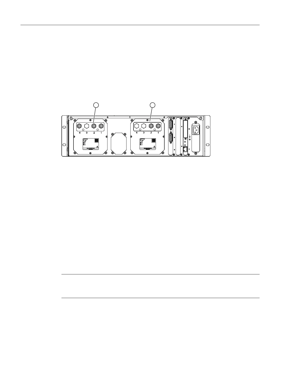
With a rack-mounted device, the gas connections are located on the rear.
The following gure shows as an example the rear of the rack-mounted device with gas
connections of an OXYMAT 7 and a CALOMAT 7.
① Slot of analyzer module 1: OXYMAT 7
Gas connections: 1 Sample gas inlet
2 Sample gas outlet
3 not assigned
4 Reference gas inlet
② Slot of analyzer module 2 CALOMAT 7
Gas connections: 1 Sample gas inlet
2 Sample gas outlet
3 not assigned
4 Not assigned
Figure4-4 Rack-mounted device: Gas connections using combined operation OXYMAT 7 / CALOMAT
7 as an example, device rear
4.6.2 Connecting signal and Ethernet cables
Note
Connecting signal cables
Install the signal lines separately from the power lines.
Connecting
4.6Connecting the rack-mounted device
SIPROCESS GA700 rack and wall mounted devices
48 Compact Operating Instructions, 06/2023, A5E35134047-AB

 Loading...


