Overview
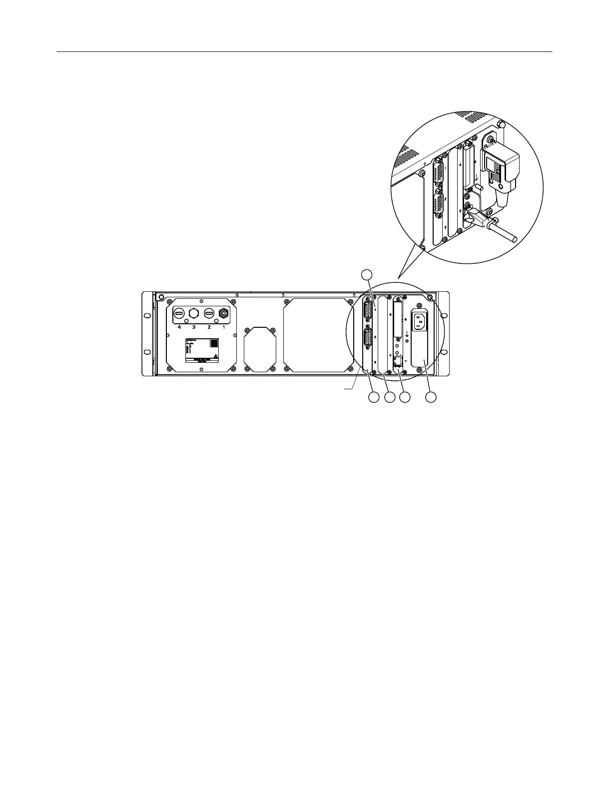
① Connector numbers
② Power supply unit: IEC connector with guard bracket (Ex-devices only)
③ Processing unit, Ethernet with interlock and 37-pin sub-D (female), digital inputs and outputs
④ Optional module 1.1 25-pin sub-D (female), digital inputs and outputs
or blank plate
⑤ Optional module 2.1, 15-pin sub-D (male), digital outputs and analog outputs
or optional module 2.2 I/O, 15-pin sub-D (female), digital inputs, analog inputs and analog out‐
puts
Figure4-5 Rear of the rack-mounted device, connecting signal cables
Procedure
1. Plug the signal cables into the associated sockets at the device rear in accordance with the
terminal assignment.
2. Screw the signal cables tight to secure them against falling out.
3. Secure the Ethernet cable with a cable tie to the supplied Ethernet strain relief. (Ex-devices
only)
Connecting
4.6Connecting the rack-mounted device
SIPROCESS GA700 rack and wall mounted devices
Compact Operating Instructions, 06/2023, A5E35134047-AB 49

 Loading...


