6. Insert the stripped conductors of the signal cable into the terminal block in accordance with
the terminal assignment (see Electrical connections and terminal assignment (Page102)).
7. Fasten the signal cable in the cable gland ③. To do this, tighten the union nut with a torque
of 4,5 Nm for plastic glands and 9 Nm for metal glands (see Cable glands (Page91)).
8. Insert the shielding plate ② in the wall-mounted device again and fasten it with screws.
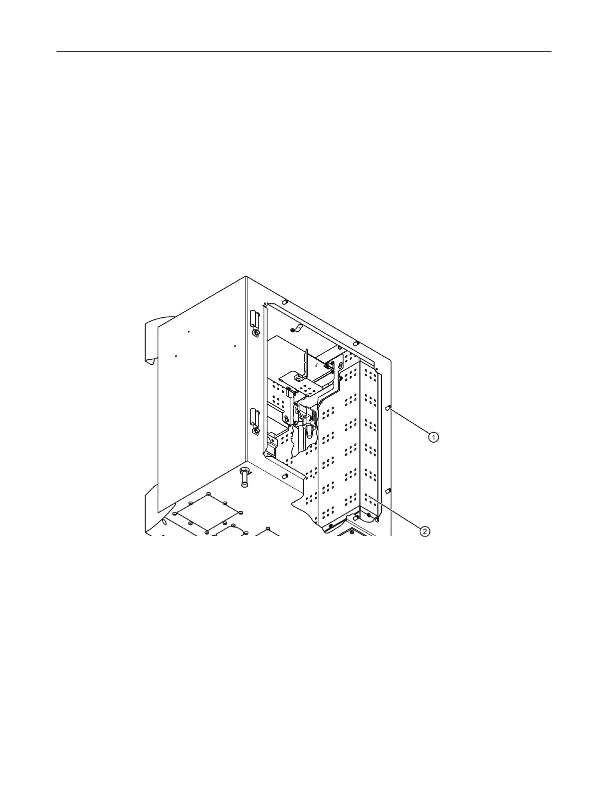
9. Close the door of the wall-mounted device and tighten the six screws ① again with a torque
of 2Nm.
4.7.4.3 Electrical connections with conduits
Electrical connections
① Door screws
② Shielding plate
Procedure
1. Undo the six screws ① and open the door of the wall-mounted device.
2. Remove the shielding plate ② on the right-side panel. To do this loosen the screws.
3. Strip the end of signal cable to a length of approx. 1 cm.
4. Remove the blind plug.
Connecting
4.7Connecting the wall-mounted device
SIPROCESS GA700 rack and wall mounted devices
Compact Operating Instructions, 06/2023, A5E35134047-AB 63

 Loading...


