Functions
2.15 Monitoring Functions
SIPROTEC, 7SD610, Manual
C53000-G1176-C145-6, Release date 02.2011
209
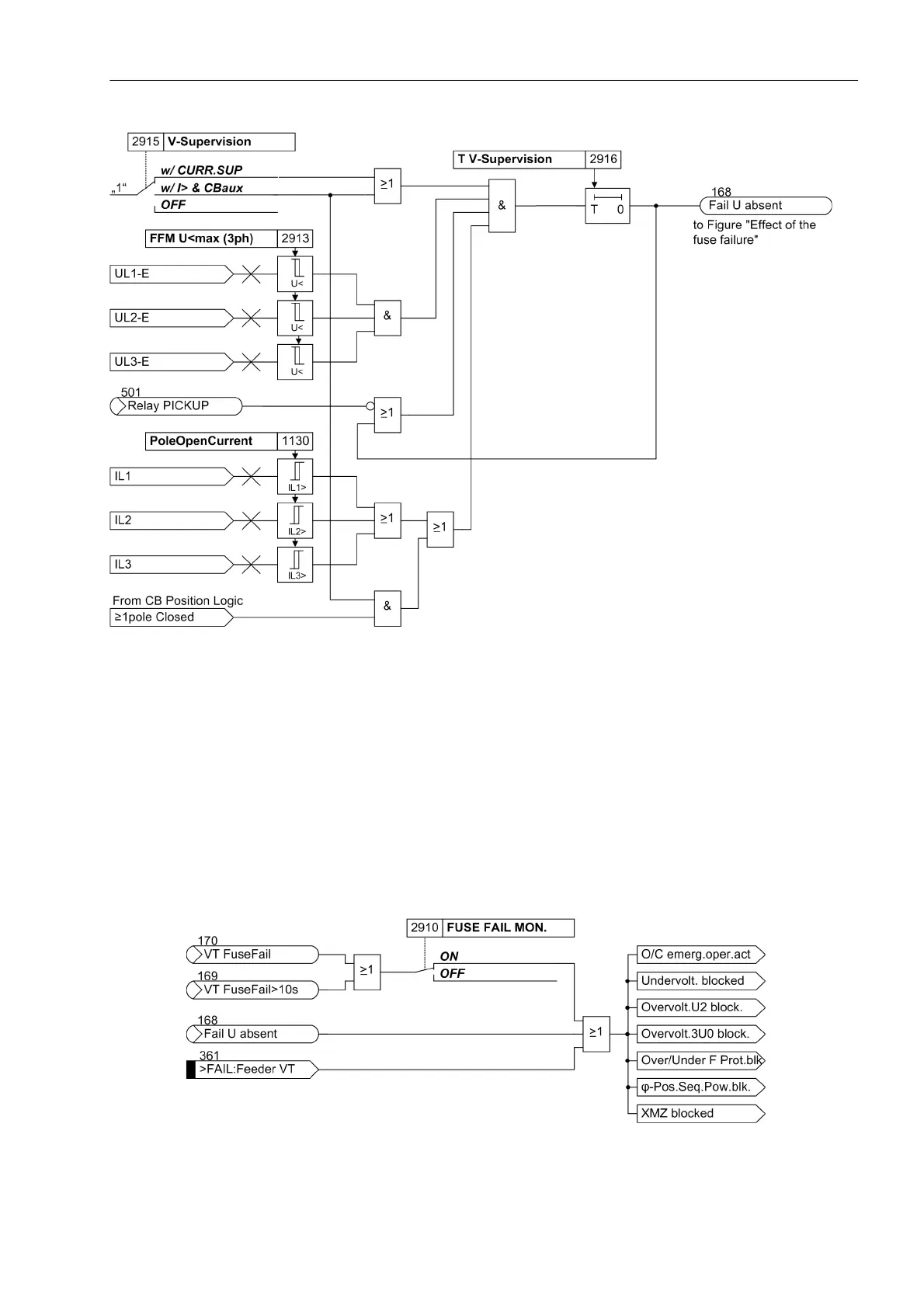
Figure 2-90 Logic diagram of the additional measured voltage failure monitoring „Fail U absent“
Effect of the Measuring Voltage Failure
In the event of a measuring voltage failure due to a short-circuit or broken conductor in the voltage transformer
secondary circuit, some or all measuring loops may mistakenly see a voltage of zero. In case that load currents
exist simultaneously, incorrect pickup could occur. If such a voltage failure is detected, the protection functions
that operate on the basis of undervoltage are blocked.
Figure 2-91 shows the effect on the protection functions in case that a measuring voltage is detected by the
„fuse failure monitor“ „VT FuseFail“ (no. 170), „VT FuseFail>10s“ (no. 169), the additional measuring
voltage failure monitoring „Fail U absent“ (no. 168) and the binary input of the VT miniature circuit breaker
„>FAIL:Feeder VT“ (no. 361).
Figure 2-91 Effect of the measuring voltage failure

 Loading...


