Mounting and Commissioning
3.2 Checking Connections
SIPROTEC, 7SD610, Manual
C53000-G1176-C145-6, Release date 02.2011
291
Time Synchronisation Interface
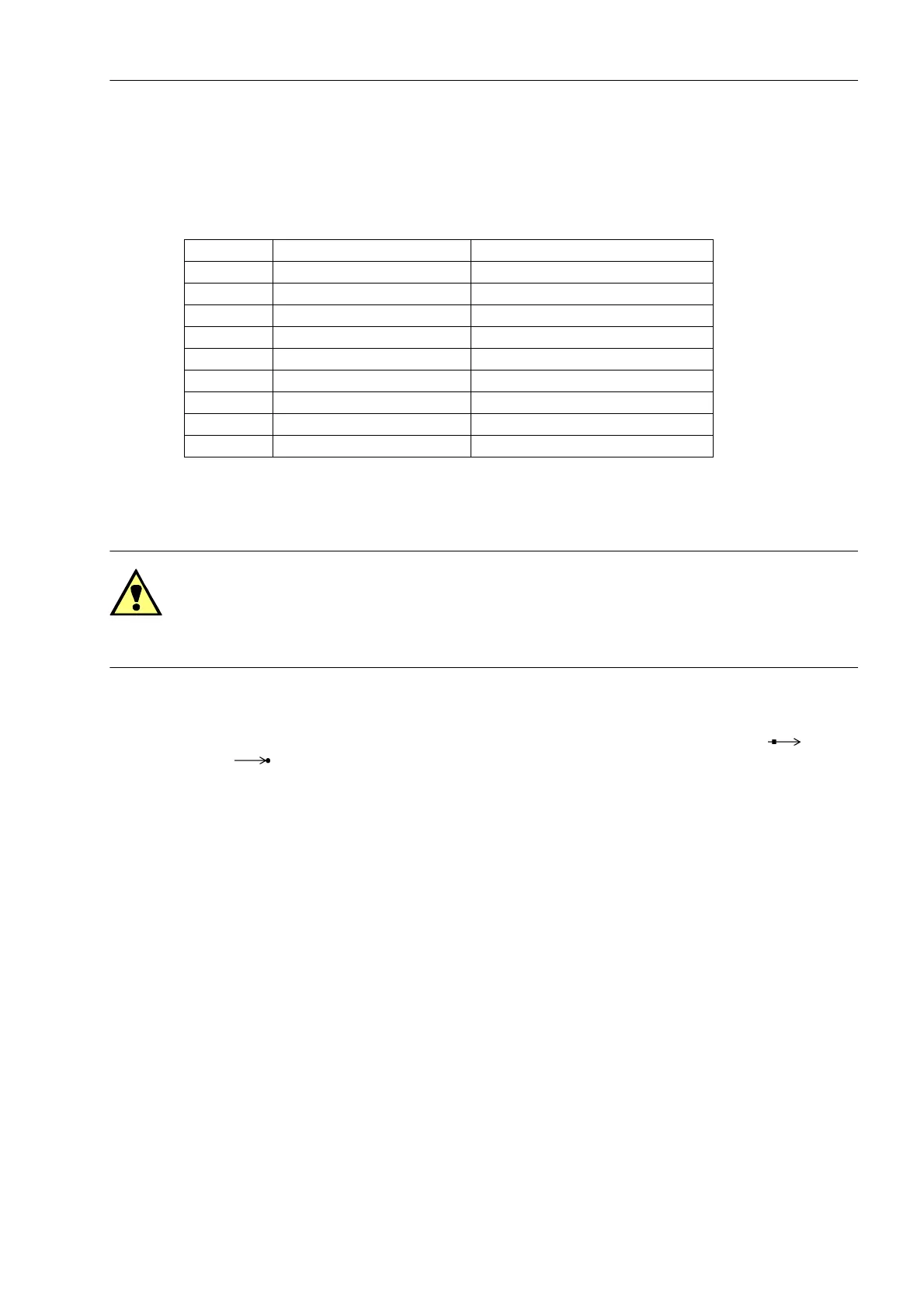
It is optionally possible to process 5 V, 12 V or 24 V time synchronization signals, provided that these are con-
nected to the inputs named in the following table.
Table 3-13 D-subminiature connector assignment of the time synchronization interface
1)
only for PPS signal (GPS)
Optical Fibres
WARNING!
Do not look directly into the fibre-optic elements, not even with optical devices! Laser class 1 according to EN
60825-1.
For the protection data communication, refer to the following section.
The transmission via fiber optics is particularly insensitive to electromagnetic interference and thus ensures gal-
vanic isolation of the connection. Transmit and receive connections are shown with the symbols for trans-
mit and for receive.
The character idle state for the optical fibre interface is „Light off“. If the character idle state is to be changed,
use the operating program DIGSI, as described in the SIPROTEC 4 System Description.
Pin No. Designation Signal significance
1 P24_TSIG Input 24 V
2 P5_TSIG Input 5 V
3 M_TSIG Return line
4M_TSYNC
1)
Return line
1)
5 SCREEN Screen potential
6- -
7 P12_TSIG Input 12 V
8 P_TSYNC
1)
Input 24 V
1)
9 SCREEN Screen potential

 Loading...


