Mounting and Commissioning
3.2 Checking Connections
SIPROTEC, 7SD610, Manual
C53000-G1176-C145-6, Release date 02.2011
290
System interface
For versions equipped with a serial interface to a control center, the user must check the data connection. The
visual check of the assignment of the transmission and reception channels is of particular importance. With
RS232 and fibre optic interfaces, each connection is dedicated to one transmission direction. Therefore the
output of one device must be connected to the input of the other device and vice versa.
With data cables, the connections are designated according to DIN 66020 and ISO 2110:
• TxD = Data Transmit
• RxD = Data Receive
•RTS = Request to Send
•CTS
= Clear to Send
• GND = Signal / Chassis Ground
The cable shield is to be earthed at both line ends. For extremely EMC-prone environments, the earth may be
connected via a separate individually shielded wire pair to improve immunity to interference.
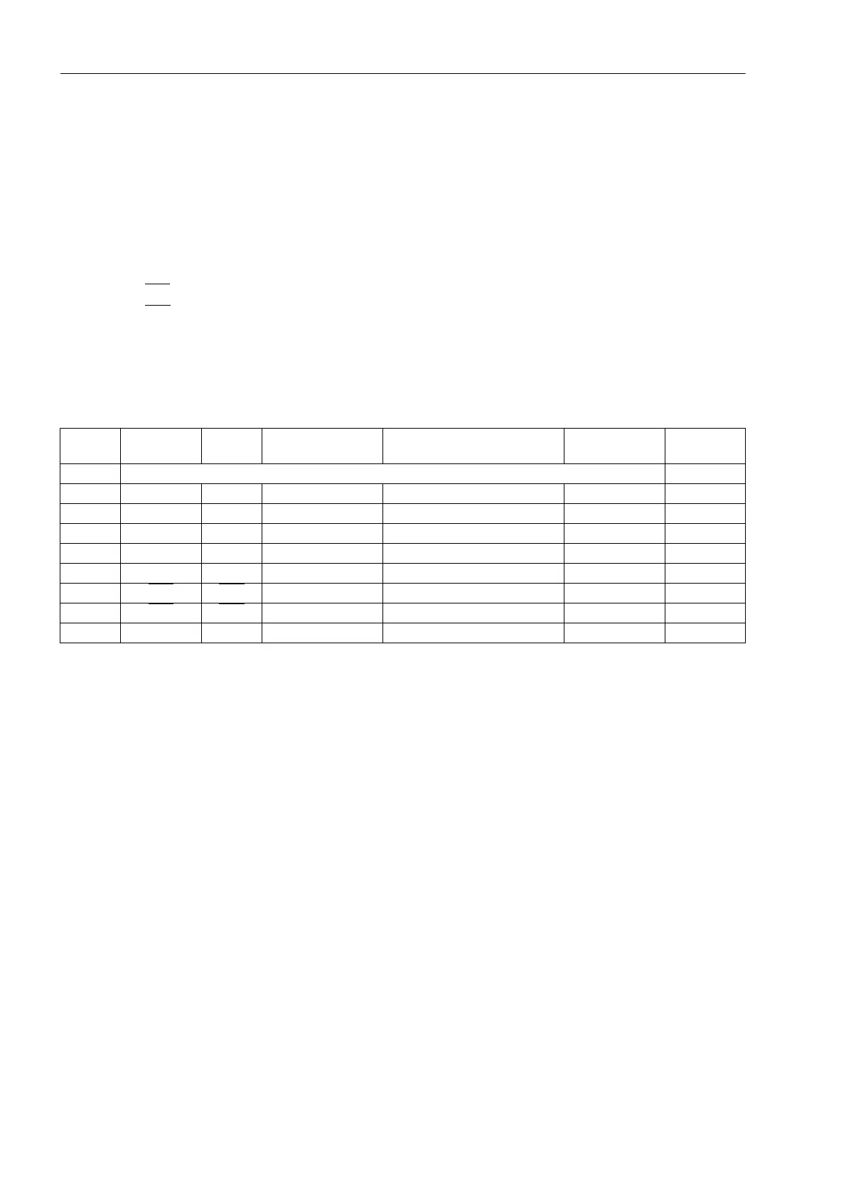
Table 3-12 The assignments of the D-subminiature and RJ45 connector for the various interfaces
1)
Pin 7 may also carry the RS232 RTS signal on an RS485 interface. Pin 7 must therefore not be connected!
RS485 Termination
The RS485 interface is capable of half-duplex service with the signals A/A' and B/B' with a common relative
potential C/C' (GND). It is necessary to check that the terminating resistors are connected to the bus only at
the last unit, and not at other devices on the bus. The jumpers for the terminating resistors are on the interface
module (see Figure3-8 or Figure 3-9) or directly on the C-CPU-2 (see Figure 3-4 and Table 3-7). Terminating
resistors can also be implemented outside the device (e.g. in the plug connectors) as shown in Figure 3-5. In
this case, the terminating resistors located on the module must be disabled.
If the bus is extended, make sure again that only the terminating resistors at the last device on the bus are
connected.
Pin No. Operating
Interface
RS232 RS485 PROFIBUS DP Slave, RS485 DNP3.0/MOD-
BUS, RS485
Ethernet
EN100
1 Shield (with shield ends electrically connected) Tx+
2 RxD RxD - - - Tx-
3 TxD TxD A/A’ (RxD/TxD-N) B/B’ (RxD/TxD-P) A Rx+
4 - - - CNTRA-(TTL) RTS (TTL level) -
5 GND GND C/C’ (GND) C/C’ (GND) GND1 -
6 - - - +5 V (max. load < 100 mA) VCC1 Rx-
7RTS
RTS -
1)
---
8CTS
CTS B/B’ (RxD/TxD-P) A/A’ (RxD/TxD-N) B -
9 - - - - - Disabled

 Loading...


