Manual 7SJ45 Construction
C53000-K1174-C001-7 49
On the front panel (Figure 2-1)the followingindication andcontrol
elements are located:
1. Mechanical trip indication (optional)
The mechanical trip indication shows whether a trip has
occurred. The trip indication is reset by pressing the key next
to it.
2. Indication of operating states
The LEDs “RUN” and “ERROR” show the operating state of
the device.
3. ENTER
This keyis used to activatethe device settings, after changing
the settings of the DIP switches.
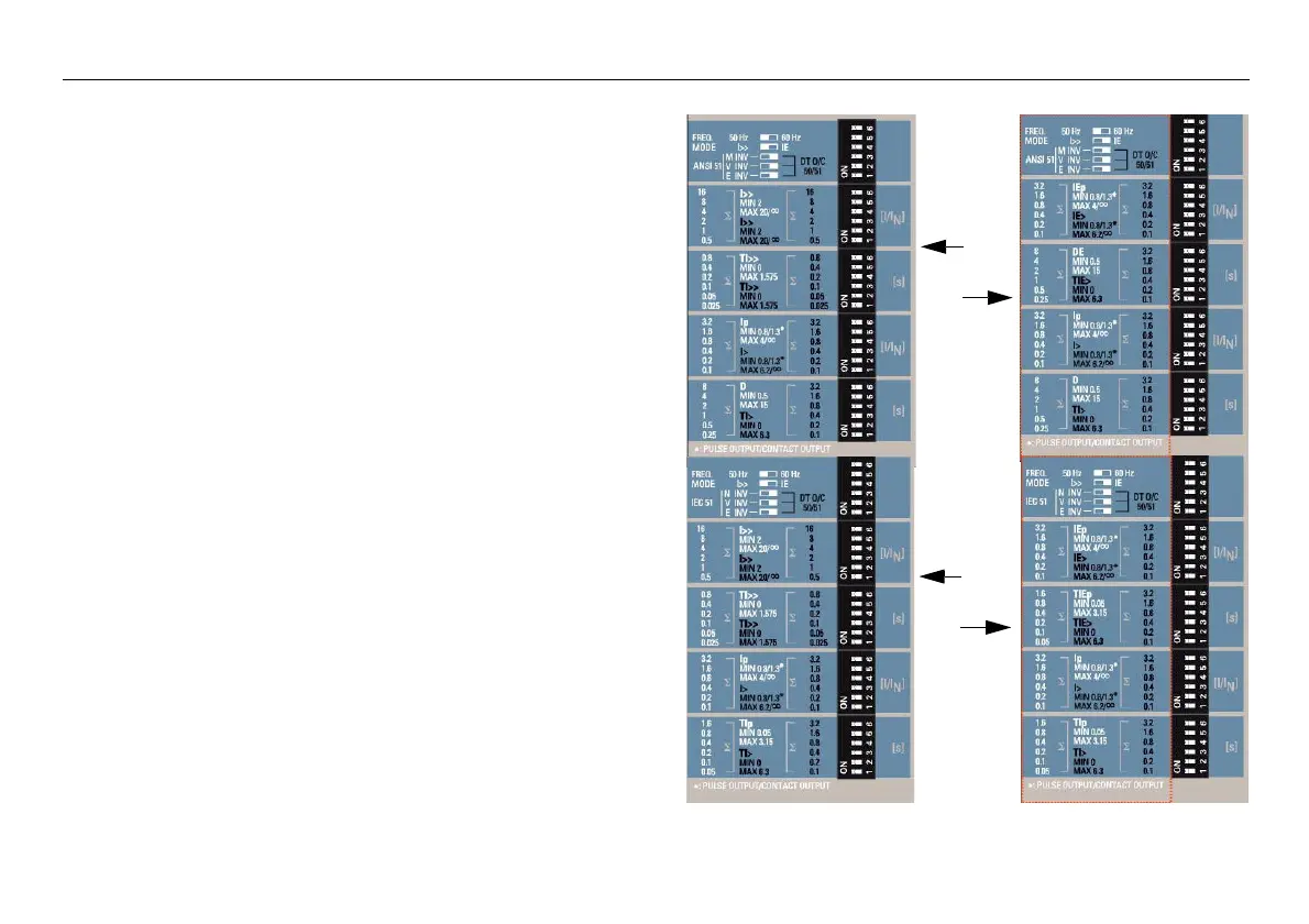
4. DIP switches
Five 6-pole DIP switches are provided for setting the device.
The possible settings are described in the section Parameter
settings.
On the back of the device (Figure 2-2), the terminal blocks with
the screw terminals are located:
ANSI
IEC
phase
earth
phase
earth
 Loading...


