Manual 7SJ45 Settings
C53000-K1174-C001-7 52
"ENTER" key to activate the modified settings. The "ERROR"
LED now stops blinking.
The following types of inverse overcurrent protection
characteristics can be selected:
The characteristics of the overcurrent protection can be found in
the section Technical Data (Figure 2-11 to Figure 2-20).
If the operating mode IEC 51 or ANSI 51 is selected, the white
marking applies for the parameter settings!
2.7.2 Parameter settings
The values that can be set are determined by the basic device
setting selected on the Basic Settings Block. The following table
shows the parameter allocation in dependence on the variant
ordered and the operating mode selected by the MODE switch:
Characteristics according to IEC Characteristics according to
ANSI
N INV Normal inverse M INV Moderately inverse
V INV Very inverse V INV Very inverse
E INV Extremely inverse E INV Extremely inverse
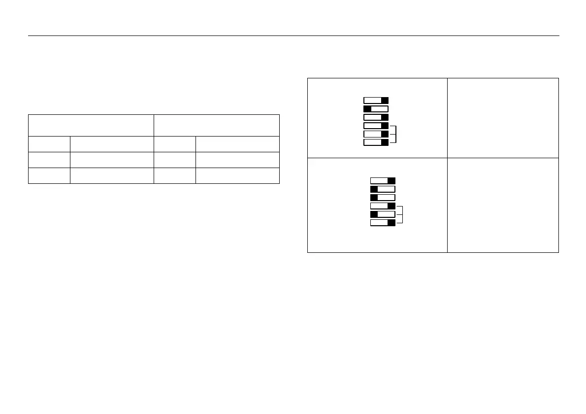
Table 2-1 Setting examples of the MODE switches
These settings mean:
Device set to 50 Hz rated
frequency
Evaluation of calculated IE
Operating mode: definite-time
overcurrent protection
These settings mean:
Device set to 50 Hz rated
frequency
High-current stage active
Operating mode: inverse-time
overcurrent protection,
characteristic type: Very
inverse
60 Hz
IE
FREQ. 50 Hz
MODE I>>
NINV
VINV
EINV
IEC 51
DT O/C
50/51
60 Hz
IE
FREQ. 50 Hz
MODE I>>
NINV
EINV
DT O/C
50/51
VINVIEC 51
 Loading...


