Manual 7SJ45 Installation and commissioning
C53000-K1174-C001-7 58
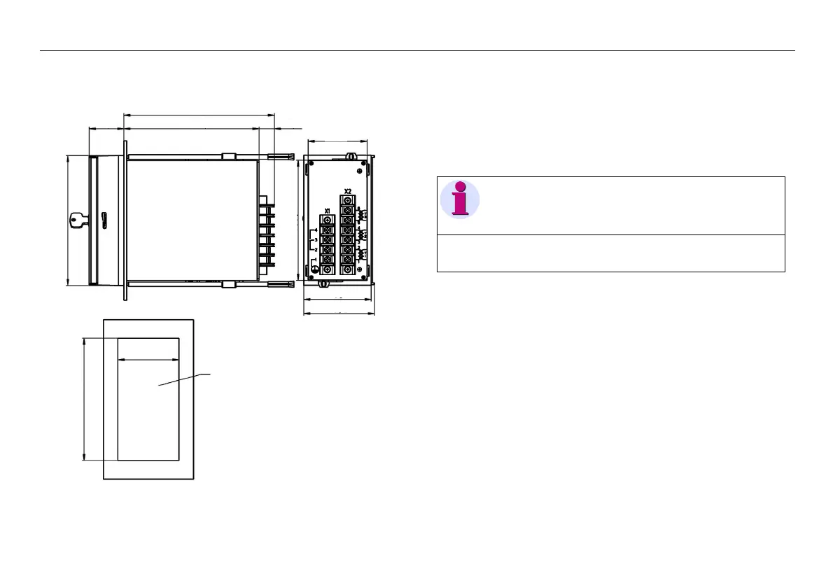
2.9.1 Panel flush mounting
Figure 2-6 Dimensional drawings
To mount the device, proceed as follows:
• Insert the device from the front into the panel cutout.
• The top and bottom of the housing have conical fastening
elements that are snapped onto the clips of the threaded
rods. The tip of the thread must point towards the device front.
• Secure the device from the back by screwing in the threaded
rods
• Connect the earthing screw on the device with the protective
earthing of the switchgear panel or cubicle
• Make the electrical connections by wiring the screw terminals
as specified in the connection diagram (see section 2.9.3).
167.3
150.238.5 17.1
65.5
75
78.5
147
Switchgear panel section72×144
DIN 43700/IEC61554
68
+0,1
138
+1
135,7
Note!
The ends of the threaded rods have a sleeve for insertion of a
screwdriver!
 Loading...


