Data in the Modbus registers
1-4
SIPROTEC Modbus - Bus mapping 7UM62
C53000-L1840-C009-03
Register map Chapters 2 and 3 define the mapping of the data objects of the SIPROTEC device
7UM62 to the associated Modbus registers.
The columns "Designation of the SIPROTEC objects" contain the texts of the SIPRO-
TEC objects for "US English" device language.
The listed SIPROTEC data objects are sorted by register numbers (starting with 1),
e.g.:
The measured value "IA S2" is assigned to register 30001 (Input register).
The single-point indication “50/51-1 Ph A PU” is assigned to register 10009
(Input Status register).
Note:
The examples shown in this chapter 1.1 do not necessarily correspond to the real allo-
cation of the objects in the register mapping.
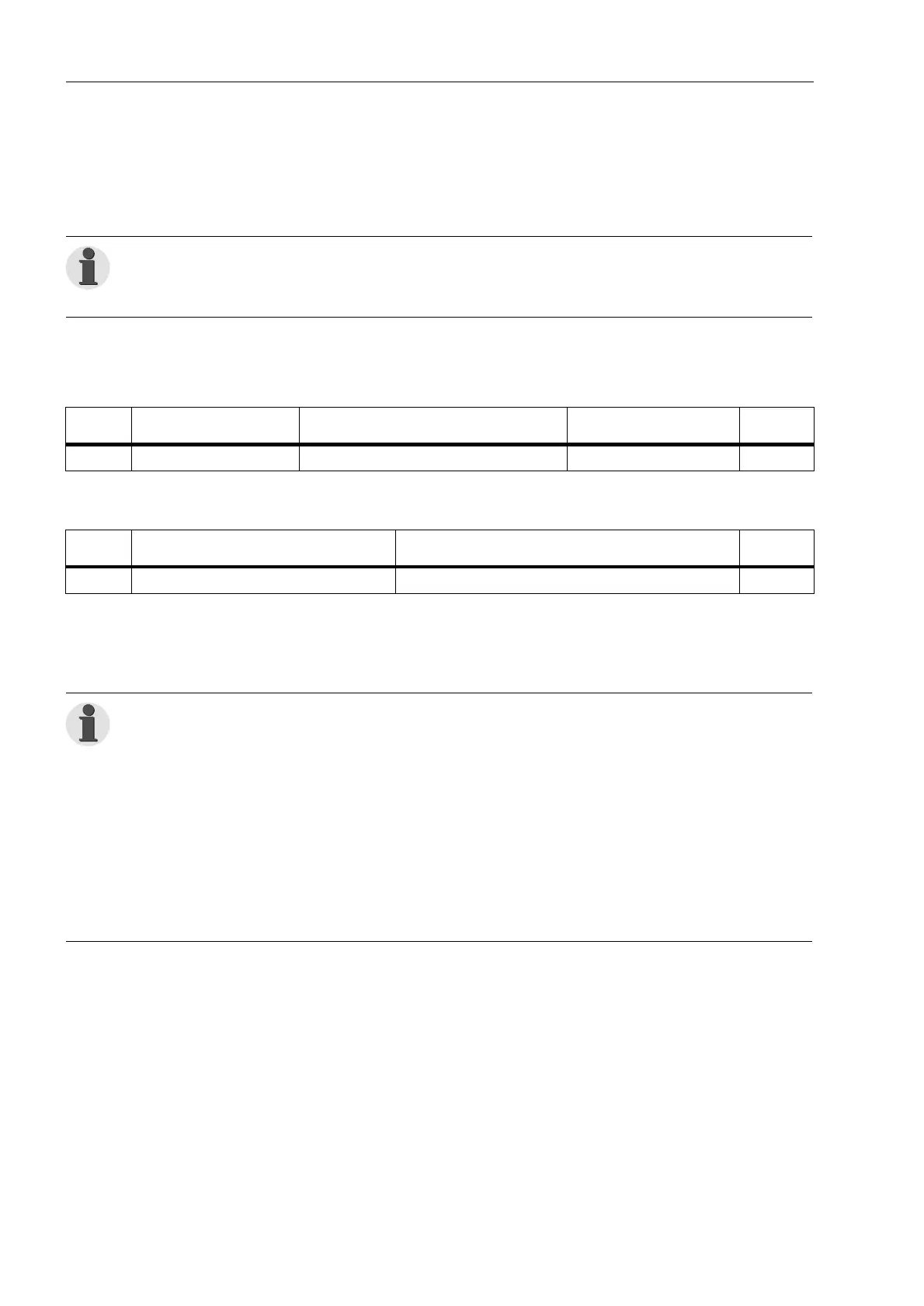
Register
Designation of the
SIPROTEC objects
Comments
Scaling
(32767corresponds to...)
Internal
object no.
30001 IA S2= Operat. meas. current A side 2 327.67 % 724
Register
Designation of the
SIPROTEC objects
Comments
Internal
object no.
10009 50/51-1 Ph A PU 1 = 50/51-1 Phase A picked up 1811
Note:
• The description of the standard mappings contains the pre-allocation of the map-
ping files at delivery or at first assignment of a mapping in DIGSI to the SIPROTEC
device.
• Changes of the allocation and the scaling of the measured values are possible in
adaptation to the concrete installation enviroment.
You find information about this in the manual "SIPROTEC Communication module,
Modbus - Communication profile" (ref. to page i).
• The definition of the data types (single-point indication, measured value etc.) are
contained in the manual "SIPROTEC Communication module, Modbus - Commu-
nication profile" (ref. to page i).
 Loading...