③ Place the connectors on the link module (U
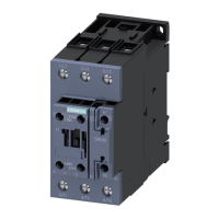
i
= 690 V), as shown in the gure, into the top main
conductor terminals on the contactor.
④ Screw the main conductor terminals tight on the contactor.
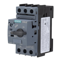
⑤ Place the reversing contactor assembly with the tted link module onto the DIN rail adapter and
guide the reversing contactor assembly onto the motor starter protector from below. Insert the
connectors on the link module into the bottom main conductor terminals on the motor starter
protector.
⑥ Screw the reversing contactor assembly to the DIN rail adapter. The reversing contactor assembly
sits tight on the adapter.
Tightening torque: 1.5 ... 1.6 Nm
⑦ Screw the main conductor terminals of the motor starter protector tight.
⑧ Attach the wiring modules for connecting the main current paths to the contactors from below.
Disassembling the feeder from the DIN rail adapter
To disassemble the feeder, unscrew the screws and pull the feeder down to remove it.
Mounting
7.3 Assembly and disassembly with dierent mounting systems
SIRIUS 3RA Load Feeders
Equipment Manual, 02/2022, A5E03656507520A/RS-AC/004 85

 Loading...


