SIRIUS 3RT2 contactors/contactor assemblies
2.4 Configuration
SIRIUS Innovations
System Manual, 01/2011, A8E56203870002-03
139
/
/
/ಫ
/
/ಫ
1
8
/ಫ 1
8
/ /
8
/ಫ 1
8
/ /
˂
8
/ಫ
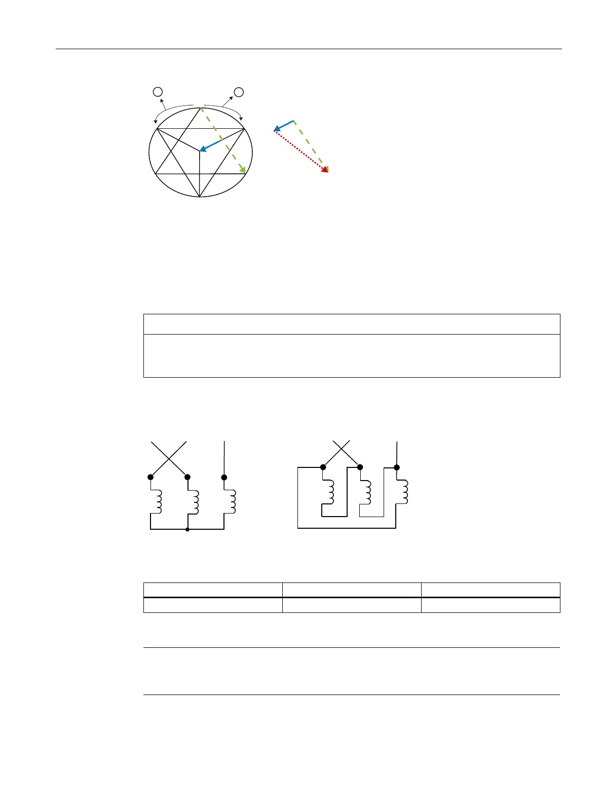
1 Rotating field
2 Rotor's overtravel during the current-free phase
Figure 2-14 Phasor diagram for motor phase connections made according to the previous diagram
results in a high switchover current peak
Changing the direction of rotation from clockwise to counterclockwise
NOTICE
In order to set the motor to counterclockwise rotation, it is not simply a case of swapping
over two phases at any location. This would result in the same conditions as those
described for clockwise rotation.
The wiring must be performed as follows in order to keep the switchover current peak which
occurs on switching from star (wye) to delta as low as possible here too:
8
9
8
9
:
:
/
/
/
8
9
:
/ / /
8
9
:
Figure 2-15 Correct connection of motor phases for counterclockwise motor rotation
Table 2- 15 Device sizing during normal starting
Star contactor Line and delta contactor Overload relay
I
e
motor x 0.33 I
e
motor x 0.58 I
e
motor x 0.58
Note
If two phases are swapped over in the network in order to change the direction of rotation,
the circuit is automatically changed/reversed from the most favorable to the least favorable.

 Loading...