SIRIUS 3RT2 contactors/contactor assemblies
2.7 Accessories
SIRIUS Innovations
180 System Manual, 01/2011, A8E56203870002-03
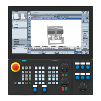
Circuit diagram
The diagram below shows an RC circuit with an RC element on the left, and an RC circuit
with a varistor on the right.
/
/
/
5B/
5B/
5B/
&B/
&B/
&B/
8
8
8
0
a
0
a
7 7 7 7 7 7
9B/
9B/
9B/
Figure 2-32 EMC suppression module, circuit diagram
2.7.4.2 Configuration
Selection aid
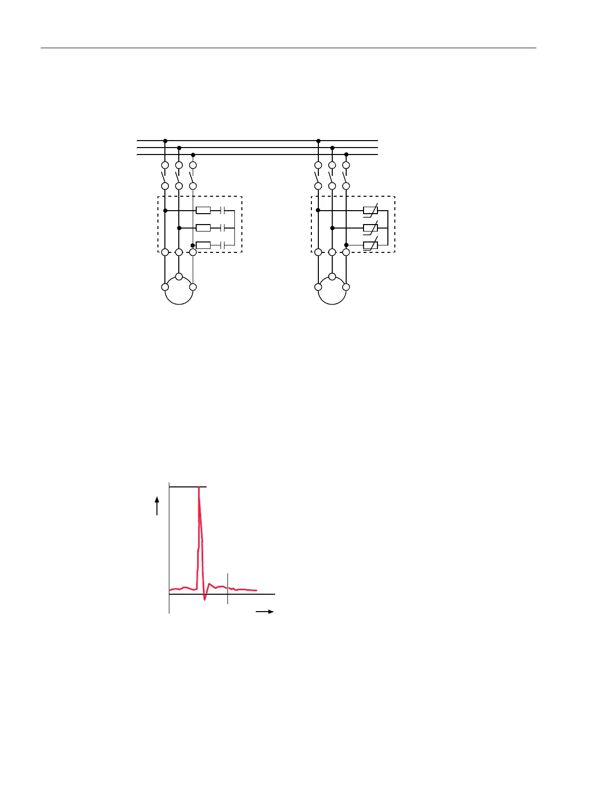
When motors or various inductive loads are disconnected, a counter-source voltage is
generated. This can lead to voltage peaks of up to 4,000 V with a frequency spectrum from
1 kHz to 10 MHz and a rate of voltage variation from 0.1 to 20 V/ns.
9
9
9
˩V W
Figure 2-33 Counter-source voltage without RC circuit
Capacitive input to various analog and digital signals makes it necessary to suppress
interference in the load circuit.

 Loading...