SIRIUS 3RT2 contactors/contactor assemblies
2.7 Accessories
SIRIUS Innovations
System Manual, 01/2011, A8E56203870002-03
177
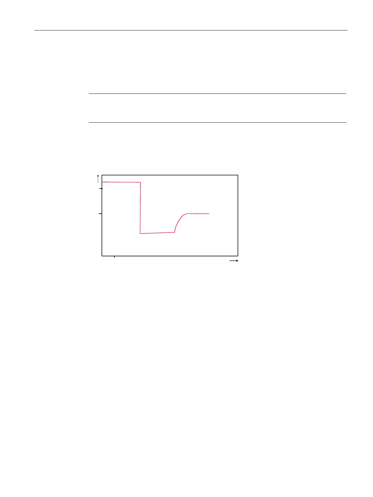
RC circuit with a diode combination
Equipping the contactor coil with an RC circuit featuring a diode combination, consisting of a
diode and a Zener diode, also ensures that switching overvoltages will no longer occur; the
diode combination limits the voltage to 10 V.
Note
The use of a diode combination does, however, extend the switch-off delay (the OFF time)
by a factor of 2 to 6.
The diagram below shows the voltage characteristic for the contactor relay magnet coil with
an RC circuit from the graphic named "Disconnection of a contactor coil without RC circuit",
with an appropriate diode combination.
8
6S
>9@
W>PV@
Figure 2-31 RC circuit with a diode combination

 Loading...