Basic Information about the Drive System
Monitoring and protective functions
7-265
E Siemens AG, 2004. All rights reserved
SINAMICS S120 Installation and Start-Up Manual, 12/04 Edition
Parameters for thermal monitoring and overload responses
S p0290 Power Module overload response
S p0292 Temperature difference alarm/shutdown threshold
S p0294 Power Module alarm I
2
t overload
S r0036 Power Module overload
S r0037 Power Module temperatures
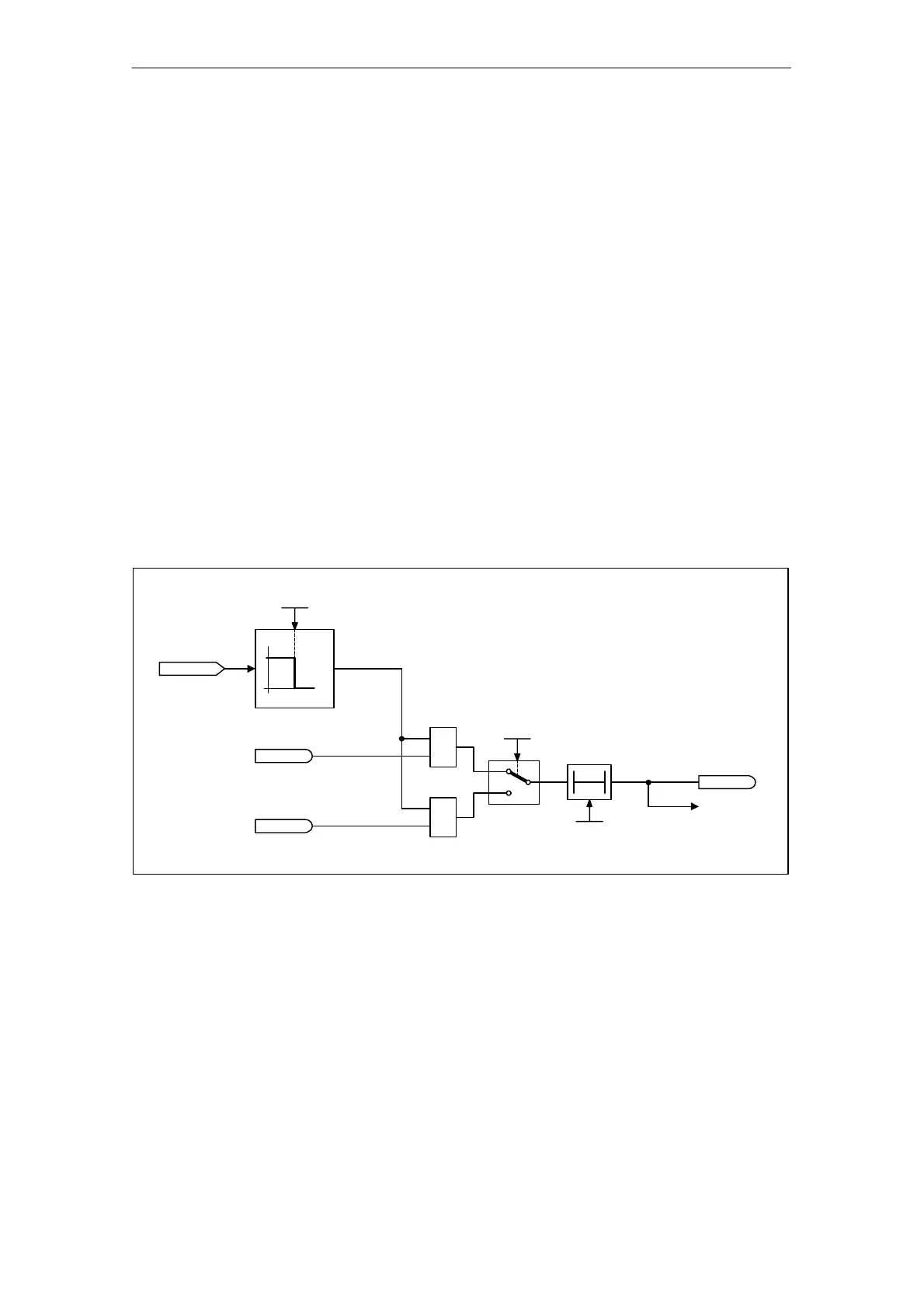
7.9.3 Block protection
Description
The error message “Motor blocked” is only triggered if the speed of the drive is be-
low the variable speed threshold set in p2175. With vector control, it must also be
ensured that the speed controller is at the limit. With V/f control, the current limit
must already have been reached.
Once the ON delay (p2177) has elapsed, the message “Motor blocked” and
fault F7900 are generated.
r2169
n_act
0.00...210 000.00 1/min
p2175 (120.00)
n_act < p2175
T0
p2177 (1.000)
0.000...65.000 s
On delay
F7900
Motor locked
r2198.6
Speed controller at limit
r1407.7
&
<20
≥
20
&
Current limit reached
r1305.12
Control mode
p1300
p1300 >= 20 –> Vector controls
p1300 < 20 –> V/f characteristics
Blockierschutz.vsd
Fig. 7-15 Block protection
Function diagram for block protection
S 8012 Torque messages, motor blocked/stalled
Parameters for block protection
S p2175 Motor blocked speed threshold
S p2177 Motor blocked delay time
 Loading...


