Commissioning
Initial commissioning using vector (chassis) as an example
3-68
E Siemens AG, 2004. All rights reserved
SINAMICS S120 Installation and Start-Up Manual, 12/04 Edition
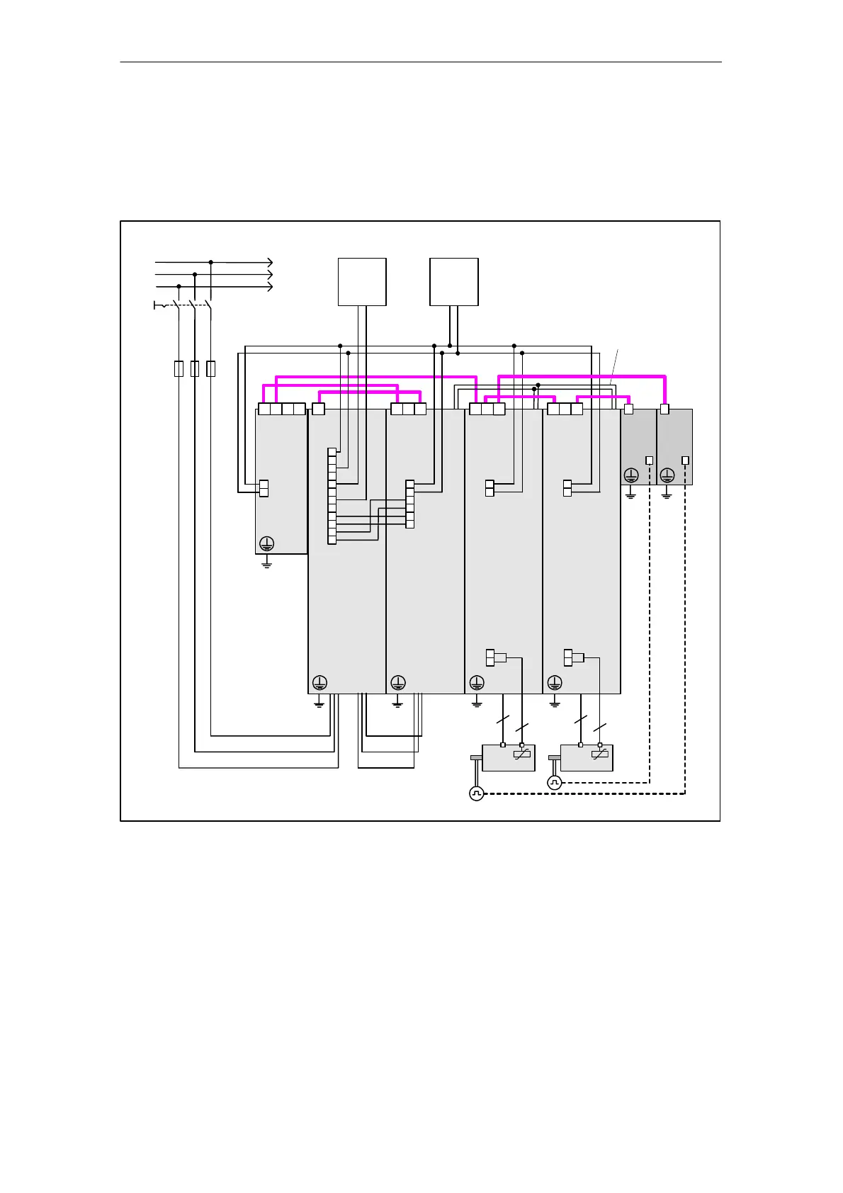
3.6.2 Component wiring (example)
The following diagram shows a possible component configuration and wiring op-
tion. The DRIVE-CLiQ wiring is highlighted in bold.
DRIVE–CLiQ
2 1
SH
X124
X100
Control
Unit
320
Active
Interface Module
X500
Motor Module
X400
Active
Line Module
X400
X609
1
3
X9
5
7
9
10
11
12
AC
230 V
external
6
5
4
3
2
1
X9
2
1
DC
24 V
external
X402
DC connection
DCP/DCN
+M
ibn_chassis_verdrahtung.vsd
LN
X41
2
1
+Temp
–Temp
1)
1) X500 on Voltage Sensing Module (VSM)
2 1
SH
Motor Module
X400
X9
2
1
X41
2
1
+Temp
–Temp
ϑ ϑ
4
2
4
2
SMC30
X500
X520
SMC30
X500
X520
Fig. 3-7 Component wiring (example)
For more information on wiring, see the Equipment Manual.
 Loading...


